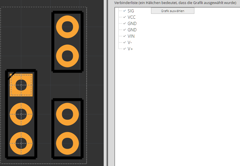
However, the pins for V+, V-, VIN and GND are assigned to something that doesn’t exist.
I somehow can’t fix that by using the “select graphic” button as it won’t show the dotted lines after clicking on the correct circle. (scrolling through the layers using SHIFT+MouseWheel)
I’m using fritzing 0.9.4 64bit on Windows10 Pro build2004 64bit, but also tried 0.9.3 64bit.
Post the svg file (you need to add a .fzp as in file.svg.fzp in order for the forum to upload it correctly, upload is 7th icon from the left in the reply menu) and I will have a look. The connectors are likely not defined correctly. The .fzpz file you are attempting to add the svg to would also be useful.
And sorry, I’m too much of a noob to upload the svg-file here It always says “couldn’t determine the file-size” on any .svg or .svg.fpz file I tried.
So here’s the svg-file in my dropbox:
The svg is fine and the part appears to be working correctly. The screw terminals are not defined in pcb (which is normal, as they won’t appear on the pcb usually) if you actually want the pads to appear on pcb (so that wires could connect from there to the screw terminals) you need to add them to the fzp file using a text editor. First you need to unzip the “IFR520 MOS module with terminals.fzpz” file which gives:
‘part.MosFet mit terminals_b5791da152ed425e080e72eb6ef246d6_12.fzp’
‘svg.breadboard.MosFet mit terminals_62039f602cf344f329aa9dd9d222f6cc_2_breadboard.svg’
‘svg.icon.MosFet mit terminals_62039f602cf344f329aa9dd9d222f6cc_2_icon.svg’
‘svg.pcb.MosFet mit terminals_62039f602cf344f329aa9dd9d222f6cc_2_pcb.svg’
‘svg.schematic.MosFet mit terminals_62039f602cf344f329aa9dd9d222f6cc_2_schematic.svg’
which is the fzp file and the 4 svgs for the part. Then you want to edit the ‘part.MosFet mit terminals_b5791da152ed425e080e72eb6ef246d6_12.fzp’ file and change connector3 to connector6 from this:
Changing the pin number to match the connector for the other pins. The original deleted these entries to suppress pcb view for the screw terminals and Parts editor can’t fix that (AFAIK). When that is done rezip the 5 files and rename it to .fzpz again and the screw terminals should appear as connections in pcb in Fritzing.
That is the joy of Fritzing parts, they carry their own source xml, so you can modify them. This series of tutorials will guide you through making parts and more or less describes the part layout:
 It always says “couldn’t determine the file-size” on any .svg or .svg.fpz file I tried.