Hello @Harald_Rau and @vanepp
at first, I would like to say thanks for your great work here!
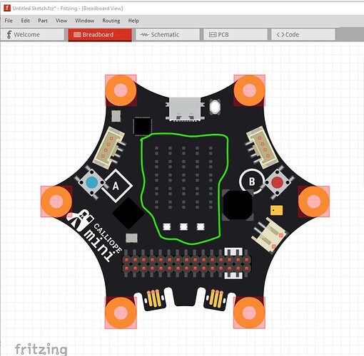
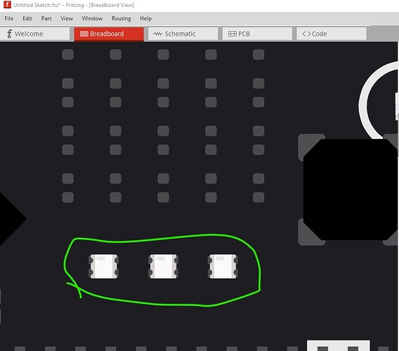
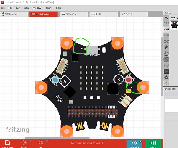
I just think I found an issue here, the LEDs on the Matrix seem to be lost in the SVG. ![]()
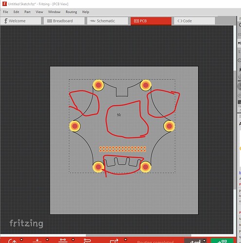
There are only the pads on the pcb visible. Could this be the case?
If they are lost in the SVG I can send you another one – or just the LEDs in the correct array. I am also unsure if you would like to have status/power/microphone LEDs included as well, as they are missing to.
Best
Joern
@JA_JA_JA Which version of Fritzing are you using? A screenshot would also help a lot. The PCB view is not supposed to render LEDs, only their pads.
On Fritzing 1.0.3 all appears well. This is the latest fzpz posted by Harald two weeks ago and all appears to be well.
In pcb view only the pins that can be connected to from pcb are shown the jadac connectors and the grove connectors can’t be connected to in pcb (as they need connectors) and thus aren’t shown there.
only the header connectors and the 6 pads that could be connected to by a shield pcb are shown.
Peter
Sorry, for not showing the case I was referring to!
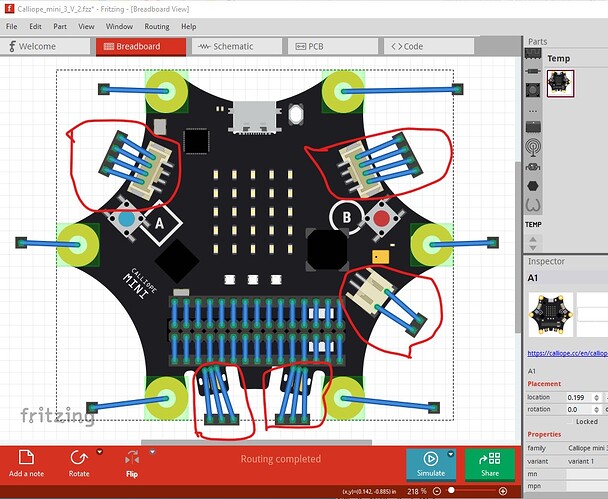
I was talking about one of the previous images from when you tried to include the Calliope mini 3
and there the LEDs have been included, later they where away…
I don’t see any images with the leds missing. I do see that there are at least two LEDs that aren’t in the svg. They can be easily added if desired though
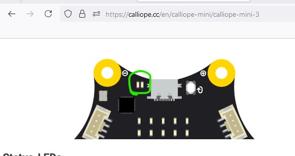
There look to be two up by the USB connector and another by the mic which aren’t on the breadboard svg
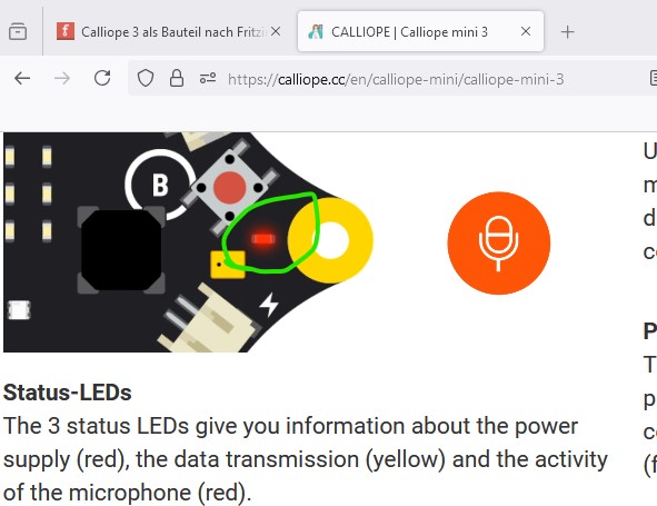
The LEDs are there in the
Calliope_mini_3_V_2.fzpz
part in the post above but missing in the latest version from Harald. I expect they can be added back in easily if they are wanted.
although I will defer to Harald on what should be done as he is in contact with the developers I believe.
Peter
I was referring to two images you have been posting. The left on is the first one (with super small logo) the right one is the current one. If you have all LEDs visible, than please ignore my post.
I am also one of the people from Calliope Harald was talking to… ![]()
Good evening,
sorry for getting back to you so late. I was cycling in Holland, a wonderful country!
The Breadboard SVG actually doesn’t have an LED. I will fix that after my vacation, but that will only be at the end of August.
Is that okay?
Best regards, Harald!
Should be fine I expect. Have a good vacation!
Peter
Hello,
I tried to install the LEDs. Unfortunately, I couldn’t use the LEDs from the original file. When I tried to insert the object, it didn’t show up. It also wasn’t a typical SVG graphic, so I couldn’t identify the type.
So, I created the LEDs myself. I hope they meet the requirements. While placing them, I tried to copy the data from the original.
@JA_JA_JA
Maybe, can you check the position of the LEDs?
@vanepp
I added the LEDs to the breadboard layer. Was that correct?
I’ll wait for your feedback and then add it to the pull request.
Best regards,
Harald!
Calliope_Mini_3.fzpz (103,0 KB)
Yes the breadboard svg is where the LEDs needed to be added. The new version looks fine to me.
Peter
OK, then I’ll wait for the response from JA_JA_JA and then change it in the pull request.
@Harald_Rau @vanepp It looks good to me! Thank you so much.
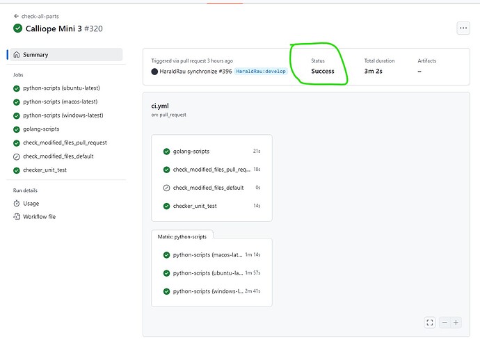
The pull request has failed.
I think the XML code is not correct. In the previous version, the “style” element was defined at the beginning of the document. The current version has a “style” element for each object again.
Are there any invalid entries in the “style” elements?
style=“fill:none;fill-opacity:0.712946;stroke:#faf1a9;stroke-width:0.773404;stroke-miterlimit:4;stroke-dasharray:none;stroke-opacity:1;paint-order:stroke markers fill”
This code is generated by my Inkscape. Is it faulty or problematic?
…and could it be the reason why the pull request failed?
Here is the svg-file
Best regards,
Harald
I exporting from Inkscape the optimized file as SVG 1.1 version.
Now the pull request was successful. I will create another fzpz version with the identical files from the fritzing-parts branch. I’ll upload it here again as well.
It looks to be successful to me.
am I missing something? I’m not all that good at github so may well be missing something. There is usually a log which tells you what it is unhappy with but I don’t see one here.
Peter
Yes, I assume everything is fine.
I just want to optimize the svg files for the fzpz file again and upload them here.
I think the pull request is successful.
Do I have to wait for the “merge” now or must i do something else?
I think you need to wait for the merge. Only someone (Kjell in this case) that has write access to the repository can merge it I think.
Peter
I have now inserted the SVG code from Git into our fzpz file. This way, we can test the merge of the pull request again later. I’ve also included a test setup, but it has no function.
Calliope_Mini_3_Git.fzpz (58,5 KB)
Test_Aufbau.fzz (109,0 KB)
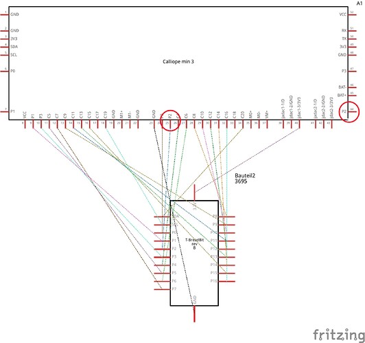
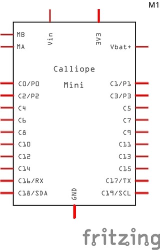
While doing this, I noticed that there are redundancies in the schematic. Is that normal, or should a schematic be unambiguous?
Maybe you could check the test setup again and discuss the question about the schematic.
Gruß Harald
I generally make the schematic match the physical layout of the board (as in this case.) Some people prefer the schematic be abstract (i.e all the ground pins be on a single pin which in the Fritzing case means the pins must overlap as Fritzing must have all pins in all views.) I can change the schematic to the abstract form if desired. I can change the schematic to the abstract form if desired.
Peter
