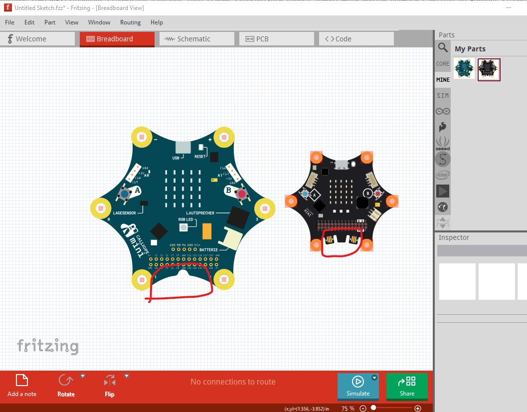
It looks like an error I didn’t notice before crept in to the Calliope_mini_3.fzpz file This is my Calliope_mini_3_V_2.fzpz file (on the right) and the Calliope_mini_3.fzpz on the left. The jadac connectors are missing in the Calliope_mini_3 part and I don’t think they should be, and there are new connectors (which I don’t think should be there) and the new part appears larger than the original, which may or may not be correct because I can’t see any dimensions for the V3 board online so it would be a good idea to print out the pcb footprint for the new version and compare it to a real part to make sure we have the size correct.
assuming that is correct I can easily move the added logo from the Calliope_mini_3.fzpz part in to my original breadboard which should cure the errors being reported I expect (although I haven’t yet looked at the breadboard file in detail.)
edit:
Looks like an error on my part. The Calliope_mini_3.fzpz I have (and used to get the images above) doesn’t match a new copy that I just downloaded which indeed appears correct. I will look over the svgs to see if I can see and correct whatever is causing the errors.
@KjellM I expect this is where the problem is (although FritzingCheckPart.py didn’t show any errors when I ran the new part through it) and I expect we can fig this up from the explanation you provided, but I think the version skew error is probably the problem.
edit2:
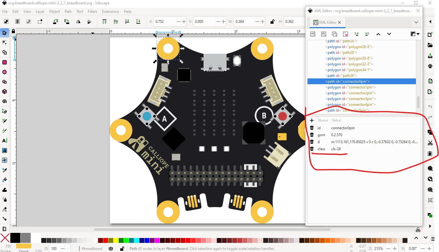
Looks like the problem is mine. I added the jacdac connectors as invisible (stroke-width 0, fill:none, stroke:none) I’ll set the fill on them all to #ffffff which should clear the problem.
OK, this part may fix the issue. I set the jacdac connectors to stroke:none fill:none (as I usually do) which is no longer legal. I have corrected that, but there may still be problems (although I hope not!) with the other pins as they appear to be using definitions for the defs section to create the parts and thus I can’t see in Inkscape if they are all visible. The easiest solution will be to extract the breadboard svg from this fzpz file and rename and replace it in the pull request and see if that clears the errors (it probably will because all the others appear to have visible .connections. Sorry for the screw up!
Could the cause be the duplicate breadboard file? It is located in both /svg/core/breadboard
and /svg/core/icon/.
In the old version of Calliope 1.3, there is no file in the /svg/core/icon directory. Maybe Fritzing automatically falls back to the breadboard file if there are errors in the icon file?
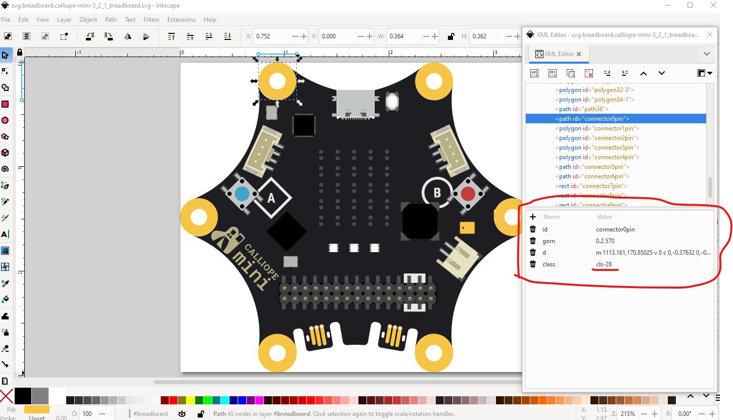
there is no fill or stroke defined, it is being inherited from the defs as cls-48 and I expect the script that checks doesn’t process the the inheritance values to see that there is actually a fill set. I will try and remove the defs (for which I need to figure out how they work exactly!) and we can try that.
I’ll go through all the relationships in the XML files again tomorrow. The error message says that the connectors don’t exist or aren’t identified.
Run python scripts/checks/fzp_checker_runner.py . -f .github/outputs/all_changed_files.json -v
Checking 1 FZP files
Scanning file: ./core/calliope-mini-3_2.fzp
Running check: missing_tags
Running check: connector_terminal
Running check: connector_visibility
Invisible connector 'connector0pin' in layer 'breadboard' of file './core/calliope-mini-3_2.fzp'
Invisible connector 'connector1pin' in layer 'breadboard' of file './core/calliope-mini-3_2.fzp'
Invisible connector 'connector2pin' in layer 'breadboard' of file './core/calliope-mini-3_2.fzp'
Invisible connector 'connector3pin' in layer 'breadboard' of file './core/calliope-mini-3_2.fzp'
Invisible connector 'connector4pin' in layer 'breadboard' of file './core/calliope-mini-3_2.fzp'
Invisible connector 'connector5pin' in layer 'breadboard' of file './core/calliope-mini-3_2.fzp'
Invisible connector 'connector6pin' in layer 'breadboard' of file './core/calliope-mini-3_2.fzp'
Invisible connector 'connector7pin' in layer 'breadboard' of file './core/calliope-mini-3_2.fzp'
Invisible connector 'connector8pin' in layer 'breadboard' of file './core/calliope-mini-3_2.fzp'
Invisible connector 'connector9pin' in layer 'breadboard' of file './core/calliope-mini-3_2.fzp'
Invisible connector 'connector10pin' in layer 'breadboard' of file './core/calliope-mini-3_2.fzp'
Invisible connector 'connector11pin' in layer 'breadboard' of file './core/calliope-mini-3_2.fzp'
Invisible connector 'connector12pin' in layer 'breadboard' of file './core/calliope-mini-3_2.fzp'
Invisible connector 'connector13pin' in layer 'breadboard' of file './core/calliope-mini-3_2.fzp'
Invisible connector 'connector14pin' in layer 'breadboard' of file './core/calliope-mini-3_2.fzp'
Invisible connector 'connector15pin' in layer 'breadboard' of file './core/calliope-mini-3_2.fzp'
Invisible connector 'connector16pin' in layer 'breadboard' of file './core/calliope-mini-3_2.fzp'
Invisible connector 'connector17pin' in layer 'breadboard' of file './core/calliope-mini-3_2.fzp'
Invisible connector 'connector18pin' in layer 'breadboard' of file './core/calliope-mini-3_2.fzp'
Invisible connector 'connector19pin' in layer 'breadboard' of file './core/calliope-mini-3_2.fzp'
Invisible connector 'connector20pin' in layer 'breadboard' of file './core/calliope-mini-3_2.fzp'
Invisible connector 'connector21pin' in layer 'breadboard' of file './core/calliope-mini-3_2.fzp'
Invisible connector 'connector22pin' in layer 'breadboard' of file './core/calliope-mini-3_2.fzp'
Invisible connector 'connector23pin' in layer 'breadboard' of file './core/calliope-mini-3_2.fzp'
Invisible connector 'connector24pin' in layer 'breadboard' of file './core/calliope-mini-3_2.fzp'
Invisible connector 'connector25pin' in layer 'breadboard' of file './core/calliope-mini-3_2.fzp'
Invisible connector 'connector26pin' in layer 'breadboard' of file './core/calliope-mini-3_2.fzp'
Invisible connector 'connector27pin' in layer 'breadboard' of file './core/calliope-mini-3_2.fzp'
Invisible connector 'connector28pin' in layer 'breadboard' of file './core/calliope-mini-3_2.fzp'
Invisible connector 'connector29pin' in layer 'breadboard' of file './core/calliope-mini-3_2.fzp'
Invisible connector 'connector30pin' in layer 'breadboard' of file './core/calliope-mini-3_2.fzp'
Invisible connector 'connector31pin' in layer 'breadboard' of file './core/calliope-mini-3_2.fzp'
Invisible connector 'connector32pin' in layer 'breadboard' of file './core/calliope-mini-3_2.fzp'
Invisible connector 'connector33pin' in layer 'breadboard' of file './core/calliope-mini-3_2.fzp'
Invisible connector 'connector34pin' in layer 'breadboard' of file './core/calliope-mini-3_2.fzp'
Invisible connector 'connector35pin' in layer 'breadboard' of file './core/calliope-mini-3_2.fzp'
Invisible connector 'connector36pin' in layer 'breadboard' of file './core/calliope-mini-3_2.fzp'
Invisible connector 'connector43pin' in layer 'breadboard' of file './core/calliope-mini-3_2.fzp'
Invisible connector 'connector44pin' in layer 'breadboard' of file './core/calliope-mini-3_2.fzp'
Invisible connector 'connector45pin' in layer 'breadboard' of file './core/calliope-mini-3_2.fzp'
Invisible connector 'connector46pin' in layer 'breadboard' of file './core/calliope-mini-3_2.fzp'
Invisible connector 'connector47pin' in layer 'breadboard' of file './core/calliope-mini-3_2.fzp'
Invisible connector 'connector48pin' in layer 'breadboard' of file './core/calliope-mini-3_2.fzp'
Invisible connector 'connector49pin' in layer 'breadboard' of file './core/calliope-mini-3_2.fzp'
Invisible connector 'connector50pin' in layer 'breadboard' of file './core/calliope-mini-3_2.fzp'
Invisible connector 'connector51pin' in layer 'breadboard' of file './core/calliope-mini-3_2.fzp'
Running check: pcb_connector_stroke
Running SVG check: font_size on ./svg/core/icon/calliope-mini-3_2_1_icon.svg for iconView
Running SVG check: viewbox on ./svg/core/icon/calliope-mini-3_2_1_icon.svg for iconView
Running SVG check: ids on ./svg/core/icon/calliope-mini-3_2_1_icon.svg for iconView
Running SVG check: font_size on ./svg/core/breadboard/calliope-mini-3_2_1_breadboard.svg for breadboardView
Running SVG check: viewbox on ./svg/core/breadboard/calliope-mini-3_2_1_breadboard.svg for breadboardView
Running SVG check: ids on ./svg/core/breadboard/calliope-mini-3_2_1_breadboard.svg for breadboardView
Running SVG check: font_size on ./svg/core/schematic/calliope-mini-3_2_1_schematic.svg for schematicView
Running SVG check: viewbox on ./svg/core/schematic/calliope-mini-3_2_1_schematic.svg for schematicView
Running SVG check: ids on ./svg/core/schematic/calliope-mini-3_2_1_schematic.svg for schematicView
Running SVG check: font_size on ./svg/core/pcb/calliope-mini-3_2_1_pcb.svg for pcbView
Running SVG check: viewbox on ./svg/core/pcb/calliope-mini-3_2_1_pcb.svg for pcbView
Running SVG check: ids on ./svg/core/pcb/calliope-mini-3_2_1_pcb.svg for pcbView
Total errors in ./core/calliope-mini-3_2.fzp: 46
Total errors: 46
Error: Process completed with exit code 46.
There are a lot of graphics in the ‘breadboard’ layer that have no connector reference. Should these be moved to another layer or to the root? So that only the id=connector can be found in the ‘breadboard’ layer?
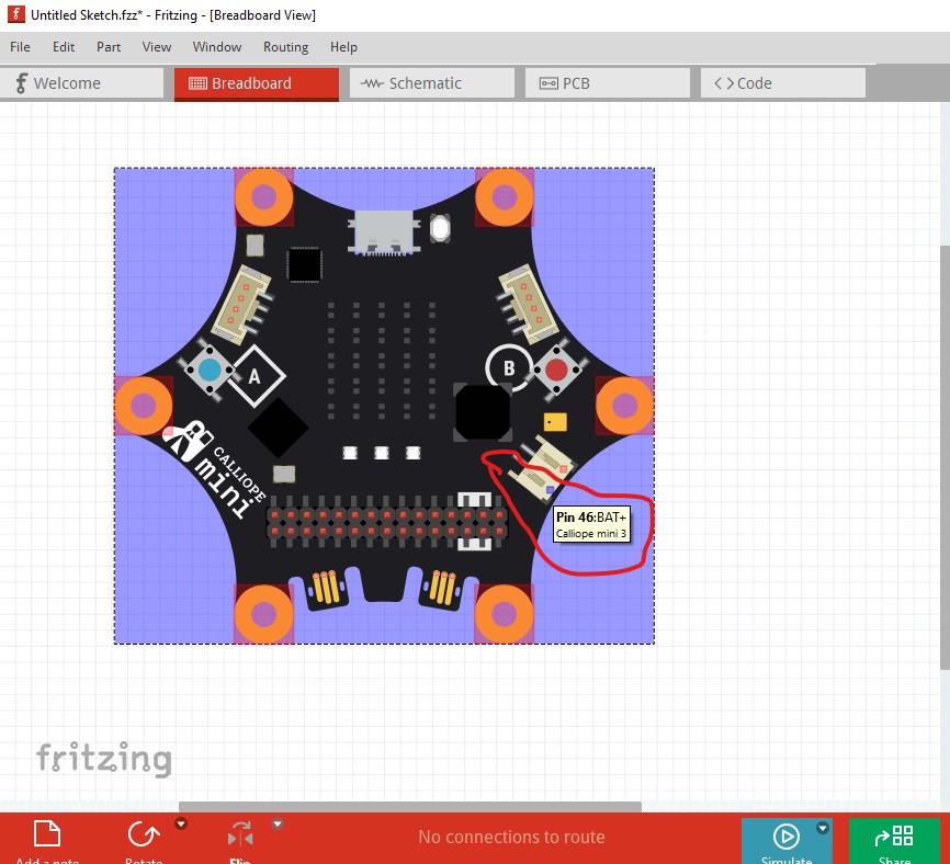
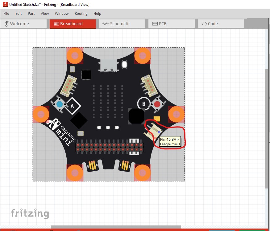
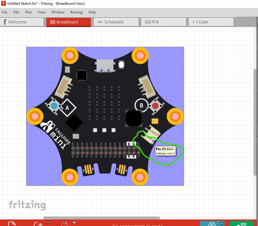
I am just testing a corrected part. I replaced the connector graphics in breadboard with equivalents that have a fill (and are not using defs which is I think what is confusing the test.) On the way by I found it appears that I got the battery polarity wrong and so corrected that (I think your change will break schematic view.) I’ll finish testing the changes and post an update in a bit
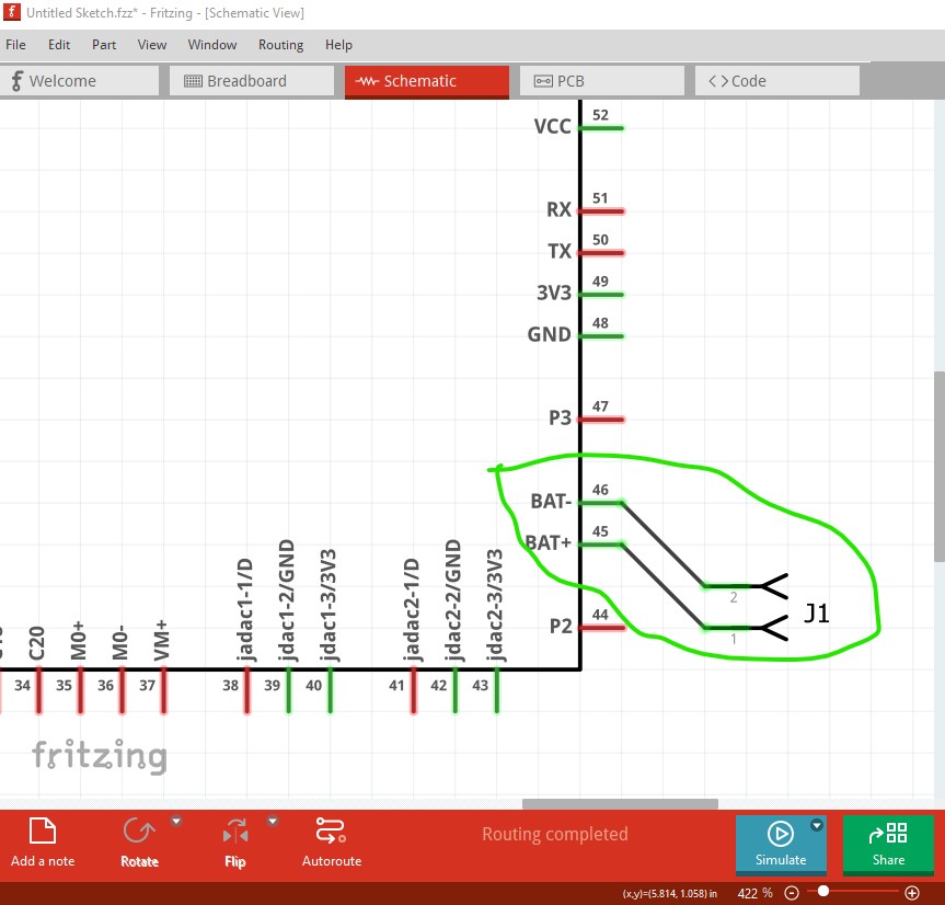
As mentioned I changed the battery connections (because it looks like I guessed wrong initially and had them backwards!) It is desirable that the pin order go up in sequence
it looks like the battery connections should be like this (you should check to make sure that is correct though!) So I changed the schematic svg to match
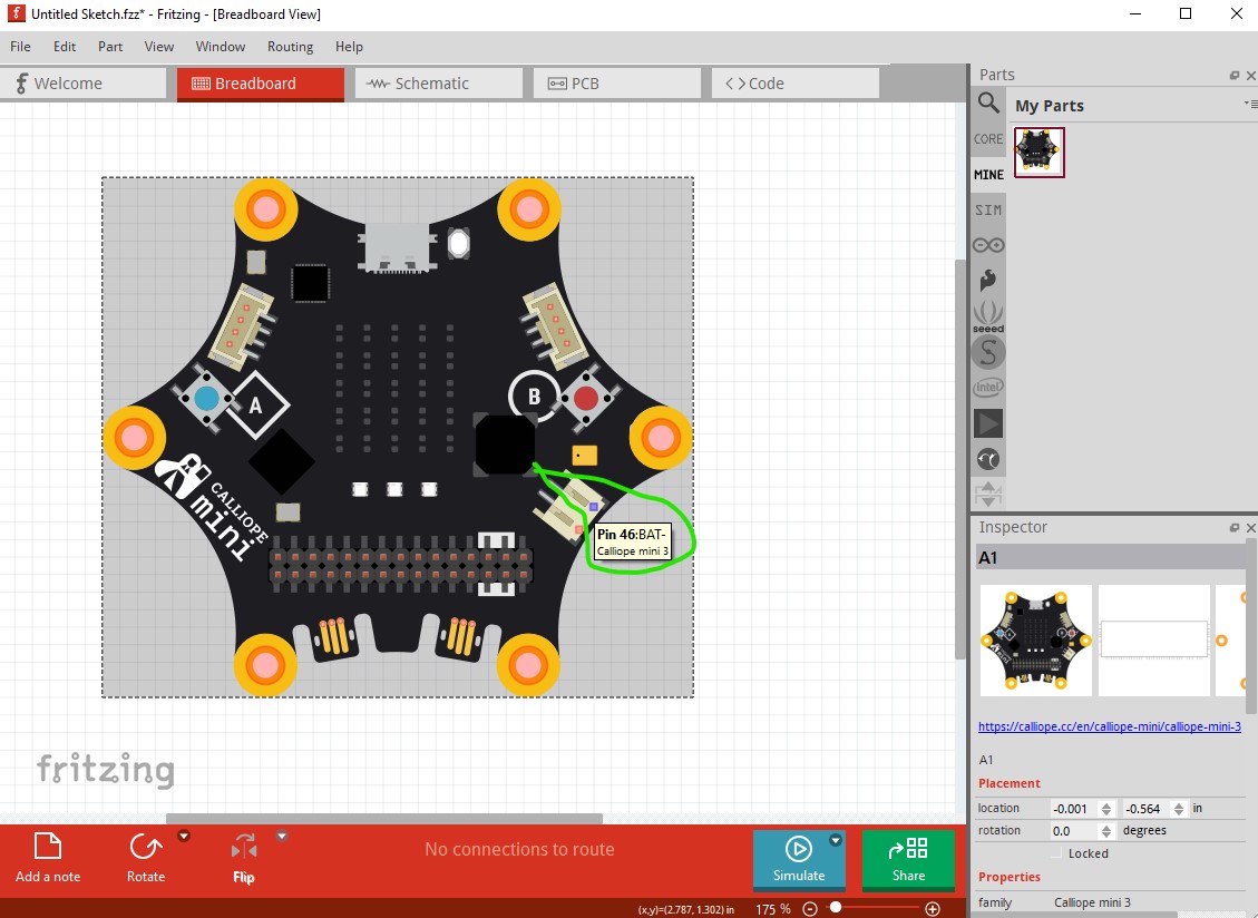
which in turn means I needed to change the .fzp file so the pin labels on hover match. On the original breadboard svg connector45 and 46 are out of order the first one should be connector45pin
The battery is correctly connected. However, I had made a mistake with the internal connections. The connection bat + does not belong in the <bus id="3V3">. So, I removed the ‘connector45’ from the <bus id="3V3"> in the fzp file.
In the downloaded fzp file and the breadboard SVG, I compared the connections and also removed ‘connector45’ from the <bus id="3V3"> in the fzp file.
I deleted the board and schematic SVG files and uploaded the new versions (Is it possible to do this without deleting them?).
I uploaded the modified fzp file (deleted the old one first).
It looks like my new ‘invisible connector’ check does not reflect how Fritzing currently treats “hybrid” connectors. Probably I need to review this check.
By just omitting the invisible connector, like jadac1-3/3V3, the 3V3 bus will not be considered.
Example:
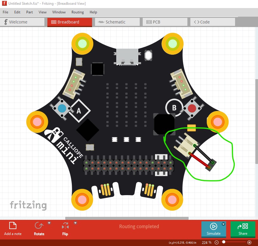
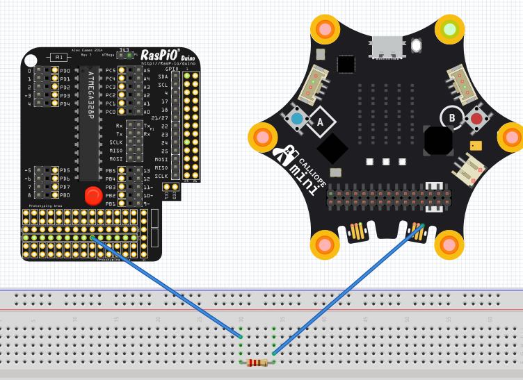
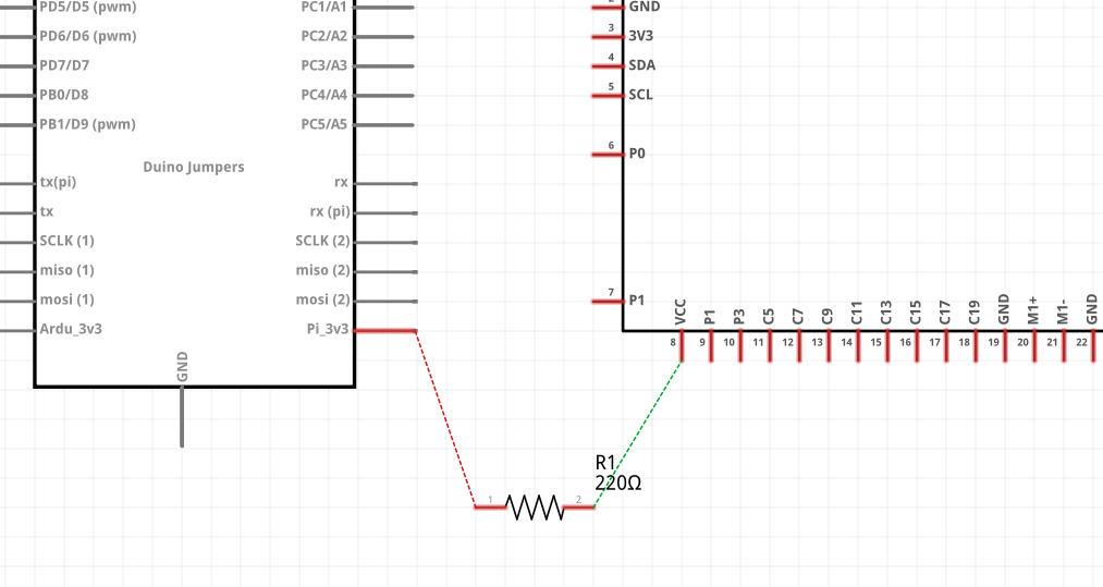
Both the RasPiO and the Calliope mini have elements, that are not intended for the PCB.
I connect them on the breadboard:
If that is correct or not is hard to say, it depends. The more “Fritzing” way would be to indicate the connection. I don’t think this is a problem of the part, but something that should be improved in Fritzing for future versions.
Do you have an opinion how the PCB ideally would look like? Do you build shields that could use the current PCB version of the Calliope?
Hello,
When the Calliope is used in primary schools, the focus is primarily on the components and the schematic.
In secondary schools, projects with the Calliope are implemented. The solution can then be soldered onto a shield.
In this case, however, you wouldn’t use a JacDac connection. The shield can’t make contact with JacDac. JacDac components are encapsulated as parts and can only be used via the JacDac connection.
I find this solution for the Calliope component perfect.
I’d agree with Harald, the jadac connectors are not accessible in pcb (which is why I suppressed them) as they are intended to connect via an edge connector cable and thus aren’t through hole so you can’t easily make a connection in pcb (similar to a screw terminal which has a similar problem.)
I found another error. On the breadboard, pin 23 (GND) is connected to JP1. In the PCB view, this connection is not routed and shows a connection from JP1 to pin 19. I am looking for the error!