Hi
I was developing a custom part for our prototyping board evive [http://evive.cc], but faced some issues of not linking some vector shapes to corresponding connectors.
I started with Arduino MEGA 2560 (rev3) in part editor and all the connectors were showing TICK mark and in BREADBOARD view, I can see corresponding crossmarks. I saved this vector image and took this as reference and build my own SVG for my board (evive). [Fig1]
Now, I did LOAD IMAGE FOR VIEW to load my SVG design. And all the CONNECTORS of ArduinoMEGA were marked correctly on my newly loaded image. [Fig2] (I am using SVG Tiny 1.2 version)
Now, I added more CONNECTORS from connectors tab [Fig3] and selected the vector shape in SVG [Fig4] then modified the TITLE in METADATA and saved it as new part (some prefix prefix000_evive_1000)
But, now I had to edit the SVG image of my design, so now I again done LOAD IMAGE FOR VIEW. But it was surprising that still the Arduino CONNECTORS are marked as earlier, but the 2 CONNECTORS which I had added were not there. [Fig5]
Then, I added the vector shapes again to corresponding CONNECTORS. But in SVG image, I named the vector shape as the connector ID (like connector380) in Fritzing and then again tried LOAD IMAGE FOR VIEW, but only the Arduino connectors were shown.
Check high resolution snapshots here: https://www.dropbox.com/sh/28r4tnxrube1dli/AAABWwt1gam6EX-lmrN8GSbra?dl=0
I cannot understand why Arduino Pins are still loading, but the connectors added by me are not shown on doing LOAD IMAGE FOR VIEW.
Please help me out.
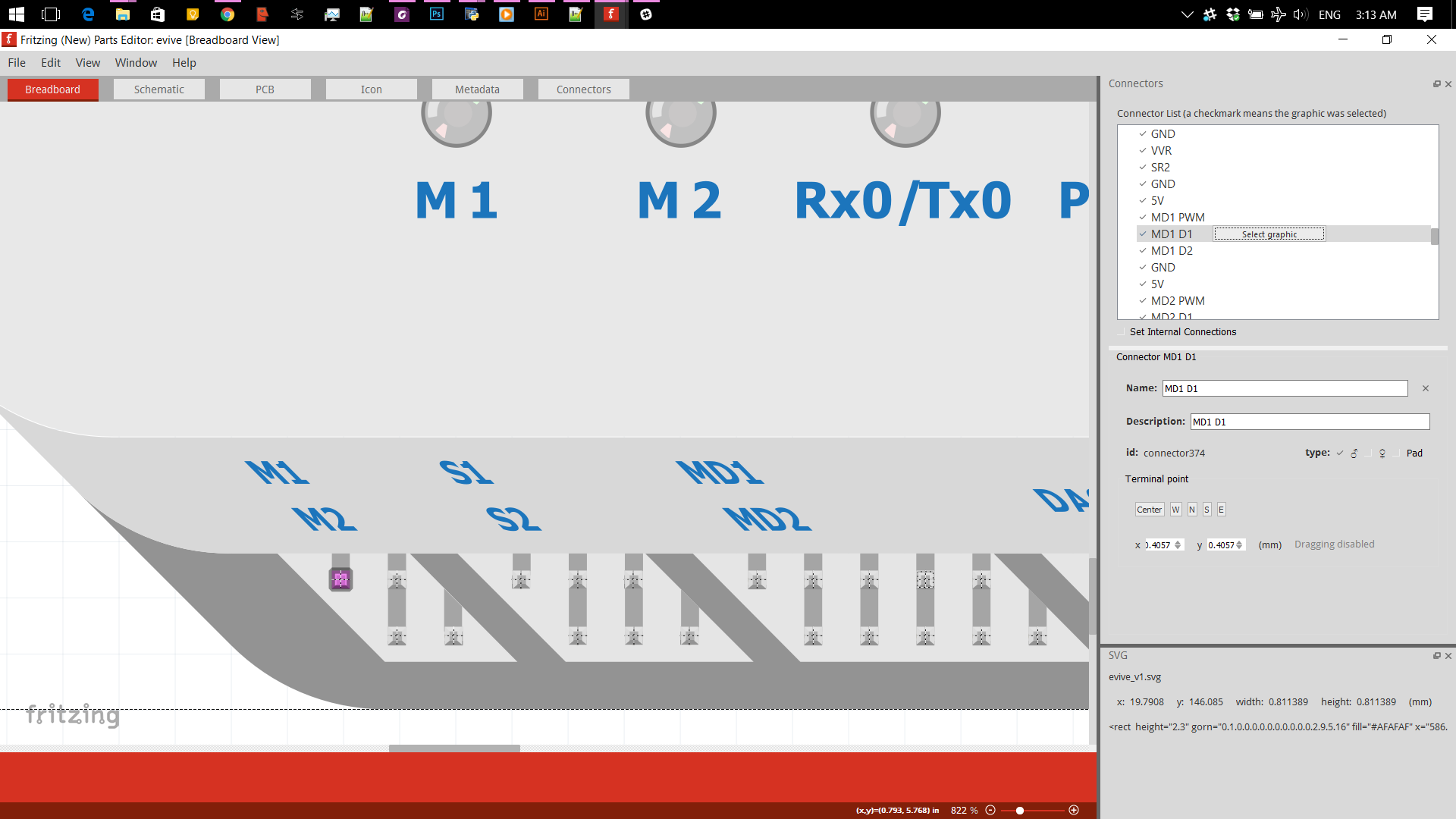
When you go Edit Part, BB view, and click on M1D1 in the top right box of Fig4, does the correct contact light up. Basically did you “Select Graphic” for the connector.
Don’t feel bad, unlike Old_Grey I have never been able to get the parts editor to set the connectors either (although he has told me how many times ). I generally hand edit the fpz file and/or the svgs to get the job done. One of us should be able to help you out if you post the part.
Do you mean the top right connector assignment box in FZ edit, like above.
Just click on the text writing - like MD1 D1 above - and the line goes dark grey. It’s the blank line with no box to indicate that you can click on it.
Then click the button Select Graphic.
Then go to the drawing and click the connector - purple square bottom left -
On the right again under the connector box you can pick Centre, N,S,E,W if you want, by clicking the boxes.
You can click on anything in the list and it will light up in the drawing if it’s assigned.
Hi
(Note: Consider XXX as part name and “XXX” as view name in Fritzing)
Thanks for suggestions. I learnt to edit the SVG and FZ part file. I was able to make the part of evive .
Now my part has a breadboard also as internal part. Everything is fine in Breadboard view. But I want to ignore terminals of breadboard in Schematic and PCB views. All breadboard (installed by default) has Breadboard view, but do neither have schematic nor PCB views. I tried to open the Mini Breadboard Part to edit, but we cannot open (Edit part option is grey).
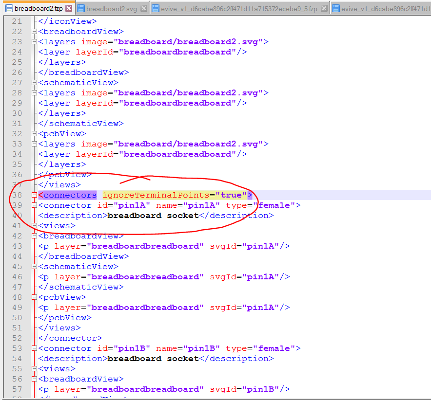
So I tried to look into the breadboard2.fzp file to see its content. There I find a difference in syntax of “connectors”. Noramally only “connectors” is used but in this Breadboard, there is "connectors ignoreTerminalPoints=“true” ".
I want to show all pins in Breadboard view, but only few in Schematic/PCB view. How to do this? I tried to use again for Breadboard pins while leaving other as normal, but It was not working (It ignored the Breadboard pins)

 ). I generally hand edit the fpz file and/or the svgs to get the job done. One of us should be able to help you out if you post the part.