I made the attached PCB File for those wanting Cutouts on the PCB for whatever reasons (including features for Parts) and Not wanting to fuss around, learning, installing software… )
It’s pretty simple:
Example:
- Know (approx) what PCB dimensions you want.
- Start a New Fritzing Sketch.
- Click the PCB and Load the PCB_4_Cutouts.SVG from the Inspector Panel.
- Resize the PCB as needed to your required dimensions (don’t worry about the existing cutout - you’ll tweak).
- Add your design/parts/etc. Layout as close to final as possible.
- Edit the PCB_4_Cutouts.SVG in your favorite Graphics Program. Move, Re-Size, Copy and Paste existing Cutouts or Add/create new ones as needed…
- Export/Save the file.
- Reload it into Fritzing and confirm all is well.
- Done * Your Exported Gerbers should be good for Laser cutting and Milling the board’s Contour with Cutouts.
Files:
Fritzing: PCB_4_Cutouts_example.fzz (2.4 KB)
PCB_4_Cutouts.SVG (delete the .fzp) PCB_4_Cutouts.svg.fzp (1.5 KB)
The file PCB_4_Cutouts.SVG has:
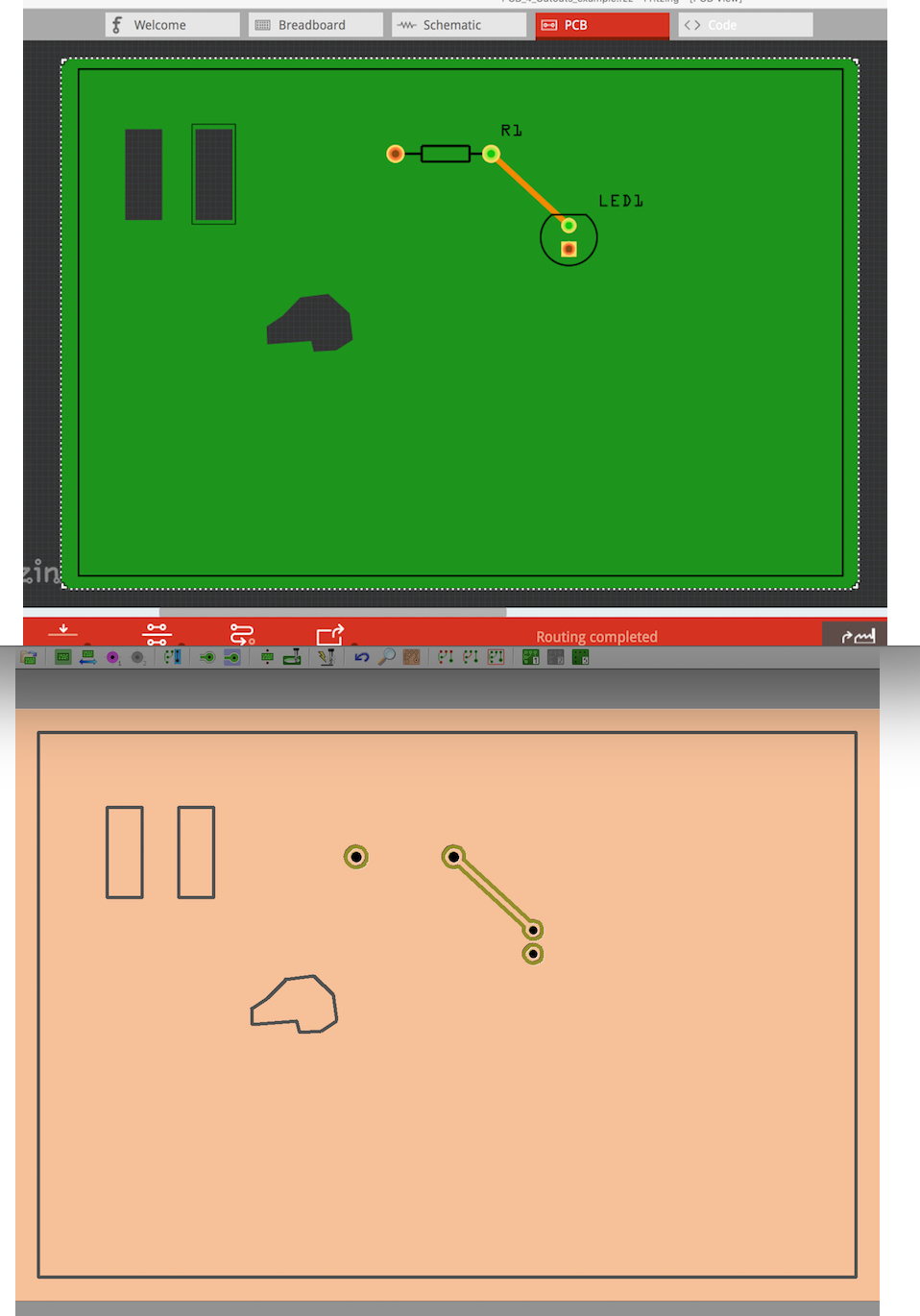
Two Rectangles and One Bezigon Line Shaped cutouts.
A Silkscreen layer with Board Shape (offset) and One Rectangle around a cutout for the Silkscreen.
Tweak as needed/indicated above…
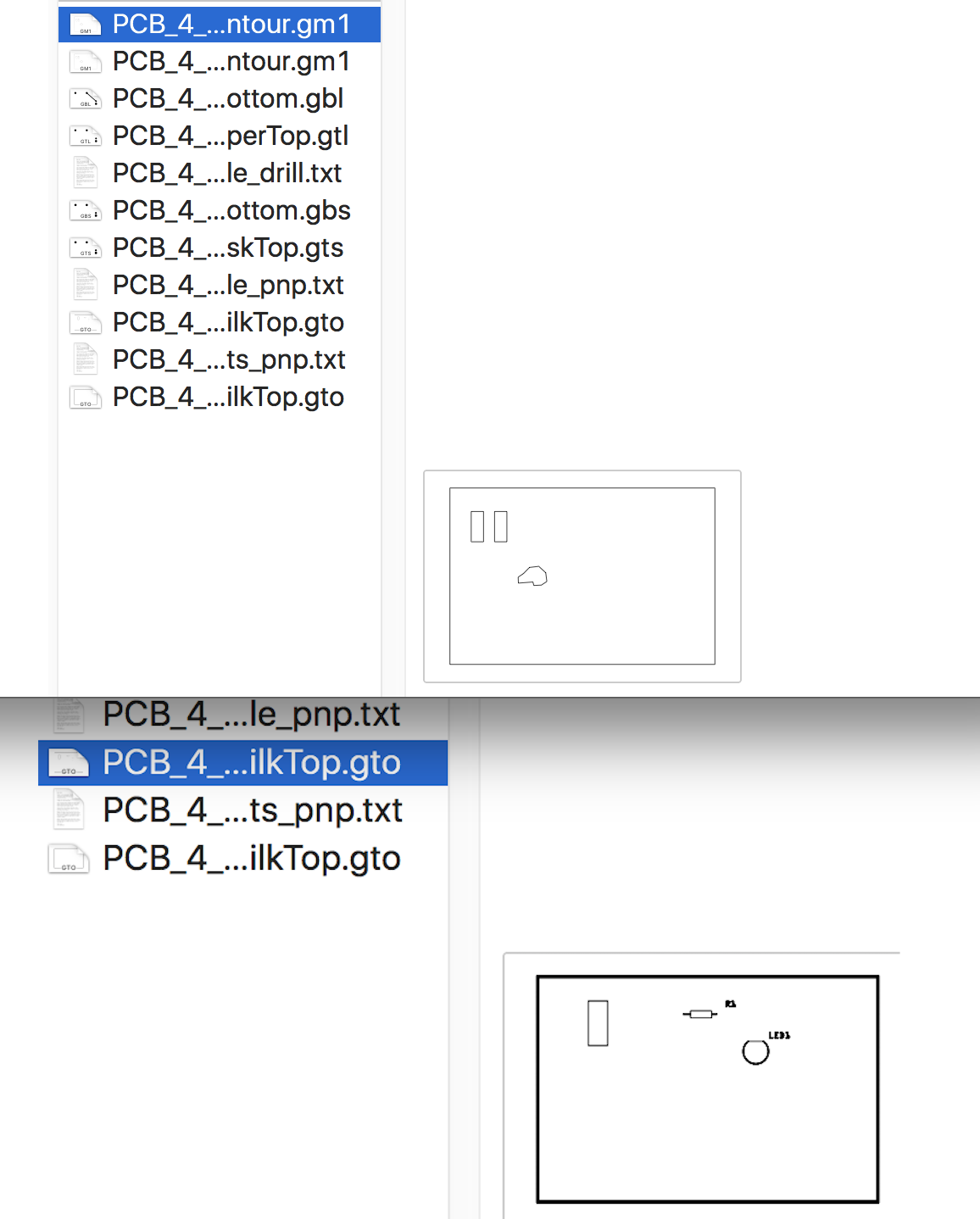
Results - Images below:
Fritzing Sketch with example and Milled simulation (CopperCam)
Gerbers of Board Contour and Btm Copper Layer
NOTE: I did not Horizontally flip the board for milling - would normally do that but was lazy for this post.
