All diodes in my left side are hurting

Didn’t want to start with “I am so depressed” (Marvin from The Hitchhiker’s Guide to the Galaxy by Douglas Adams), but I am slightly miffed.

I want to repair an old game console (a PONG-like CONIC box) for Awesome Space in Utrecht, and for this I want to trace part of the PCB. Now I do also want that schematic to look nice - so I need some PCB CAD software.

From Ubuntu, I know KiCAD, but I could not successfully install it (looks like something is broken with the binary file generation for Win64).

Looking for alternatives, I found Fritzing.

And I recognized the style of some Arduino and breadboard layouts I have seen in the past, so why not giving it a a try.

Ok, the first ‘interesting’ thing is the Paywall. EUR8 is not much, thought, and I do understand why you need to ‘ask’ some money for the download.

What drives me slightly mad, however, is that I can not just pay 8EUR, and download a file.

To pay I DO need to sign up with PayPal. It is not possible to pay as a guest (anymore?).

Now that’s not the biggest evil of all time or something, but I do not like to be forced to something. Most people don’t like that. I am no exception. I nearly walked away.

Not happy.

Apart from that, I am a normal guy, born in DE, living in NL since 2015, day job is developing software for both embedded systems and a full-stack setup. I like tinkering with electronics and FPGAs, retro games (and new ones).

Regards,
Tagon

Down the bottom of the PayPal mine says you can pay with card.

I only do small stuff so FZ is more than enough for me - FZ is simpler if you don’t need to make parts -, but this sounds big so I would be inclined toward Kicad. I have KC 5.0 working fine on Win7 64 so maybe ask their forum.

Yes, it says you can pay with card. After I entered all my data, PayPal told me I need to sign up. There was no way to ‘skip’ this. Quite annoying.

But I managed to trace most of the Conic TG-612 board quite nicely with Fritzing, so it proved useful. Also I could make a video amplifier schematic.

As I see it, the Fritzing schematic editor is OK to work with. I find it cumbersome its not possible to just connect components to existing wires without first ‘pinching’ the wire to make a connection point. And then you need to adjust the connection to snap back to the grid. Also when moving components the wires usually go quite haywire.
Maybe I’m doing something wrong. But it works well enough for the purpose, and I have seen a few Arduino wiring diagrams made with it, so hope to gain more from it in the future.

Background:

We want VBS (BAS) output instead of RF output on TV channel 2 or 3. The Conic chip (a GI AY-3-8500) provides a VBS signal, but at the connection point I want to use, the signal is too weak, only 348mV instead of ca. 1V needed for VBS (=picture too dark, and on some TVs it does not even sync). So I need to build a small video amplifier.

Turns out there are a few (cable) video amplifier designs around, but most of them for a 12V supply, I only found one for 5V.

The Conic internally stabilizes its 9V feed to ca. 6.25V (it has a simple linear regulator built from a 6.8V Zener diode, a 560Ohm resistor and a small transistor).

When I (breadboard-) built the video amp, and hooked it up, its output was permanently stuck to almost 6V, so I needed to tune/change the design.

And for this I wanted circuit simulation. With a complex Video/Blank/Sync waveform, that comes at about 16kHz line frequency plus pixel clock up to 12MHz, a multimeter just won’t cut it. I only have a tiny handheld HPS40i oscilloscope - this was already very useful, but it’s too twiddly to do intensive component parameter testing with it.

Simulation can help here a lot, because changing components is very fast, and you can monitor waveforms quite easily.

Luckily, meanwhile I managed to download KiCad from a Cern server, and that binary installs without problem on Win10/64bit. It comes with ngspice, so I entered the video amp in KiCad and tried to simulate it.

And it failed most of the time, because of some transients simulation issue. Seems to be quite a common problem with SPICE. (A couple of years ago, I have done some circuit simulation with QUCS, but never ran into a simulation problem there. It was also very simple, only one transistor and a couple of resistors.)

Well, I got it to work eventually, but it’s hard to verify the component SPICE models I have are matching the real-life components on the breadboard.

Years ago, I got a book that came with an ‘Electronic Workbench’ . I remember it was quite nice stuff. So I tried to install this (old) software. Turns out it cannot run with Win10/64bit. And ‘EWB’ seems to have been absorbed by Multisim, and that is now part of National Instruments (now called NI).

So finally I got the 7-day trial version of Multisim 14.2 to simulate the circuit and try to adapt its components to a higher voltage.

Multisim also had a problem at first - (timing step too small). But it comes with an ‘assistant’ that automatically tries to resolve these simulation issues. Quite a clever tool: it systematically changes some SPICE parameters (e.g. RSHUNT), and if at some point the issue is resolved, it goes back and tries to revert anything it changed before the latest change, to get to the smallest set of changed parameters. Nifty!

That simulation is also not perfect (at some point I had really weird output on the simulated oscilloscopes, and I knew this had worked before – so I did what software developers often do: I restarted everything and then it worked again…), but with Multisim being a quite expensive commercial product (with a hefty price tag), I have the feeling that their component database is quite accurate.

Eventually I had a set of component values that seemed to do what I needed - amplify the input signal by a factor of (about) three. Nice!

Next stage was modifying the video amp on the breadboard, and testing it with the real Conic hardware.

Which did not work at first. For the simulation, I had added some resistors to get a defined input/output impedance, and I also added an output capacitor.

In the real world, these needed to be removed (one reason is probably that the Conic RF modulator circuit already puts some load on the VBS signal, so I don’t need an ‘input load’ resistor – for the simulation it is crucial to have, however).

Now the next step (=to do) is to convert my breadboard design to a physical PCB. Probably I will use a small piece of stripboard (I got some here).

But - hey! - in Fritzing that you can design a PCB, Schematic and Breadboard from the same circuit. So I wanted to try that first.

Schematic view… OK, that’s what I already used a lot. A bit quirky, but works.

Trying the Breadboard view… I gave up on this for now. Which is a shame, as I would have liked to document my existing breadboard layout.
But it looks like you cannot change the viewing angle of the breadboard (eg. view components from the top), and then there are just too many components in the way of each other. Resistors and capacitors can be really small on a real breadboard (folded-in), but not in the Fritzing view. I tried to horizontally flip an electrolytic capacitor, but that is just ugly. Not suitable to how I work. Too much time fiddling around and not really seeing what I’m doing there.
Maybe I’ll try this for some Arduino connection diagrams in the future, but for my video amp it feels too much work for too little gain.

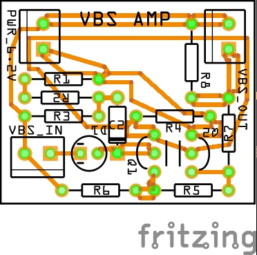
Trying the PCB view… quite nice, especially the autorouter. The PCB looks quite OK. A bit weird that I cannot restrict routing to one layer only (the design is really simple), and also I did not see an option to e.g. place resistors ‘standing up’, but it’s a good effort. I don’t know of a local service that works fast and is reasonably cheap, so it probably does not make sense for a one-time-only thing to order a PCB made, so for now I’ll probably go with my trusty stripboard.

Trying the stripboard view… unfortunately Fritzing does not have one. Hmmm… what a pity. Back to LibreOffice Impress and an old template I made that works quite well… :slight_smile:

Most of that is above my pay grade :slightly_smiling_face: but I do know a bit about FZ.

Most of these problems will be covered in the vid I’m now making, but
Search the forum for top view parts. These are smaller from the top, but you can’t make them shorter useless you redraw the part view.
In PCB view select the bottom view at the bottom left, and all traces end up on one side.
Standing up parts should be selectable in the Inspector when you put a resistor on the PCB, and if it’s not search the forum for it.
Stripboard is at the bottom of CORE parts, or is selectable in Inspector.
I think junctions losing snap is intended so you can see the connections when you move it.
Another FZ feature is click on a pin and everything connected turns yellow.

Most of that is above my pay grade :slightly_smiling_face: but I do know a bit about FZ.

Ahem… you seem to know a lot about FZ. Many thanks for your tips!

Search the forum for top view parts. These are smaller from the top,
but you can’t make them shorter useless you redraw the part view.

Will do.

In PCB view select the bottom view at the bottom left, and all traces end up on one side.

Hmmm… did not work when I tried it - but another of your remarks lead me to the solution:

In PCB view, you can click on the PCB itself, and in the Inspector pane property ‘layers’ you can select ‘one layer (single-sided)’ or ‘two layers (double-sided)’.

Standing up parts should be selectable in the Inspector when you put a resistor on the PCB, and if it’s not search the forum for it.

Nice - I found Breadboard Top View Part Collection | #4, created a new bin “Top View” and imported " 10. Top View - Electrolytic Capacitor.fzpz (6.7 KB)".

Problem: When I change the value of the component from 1uF (default) to 10uF, Fritzing replaces the top-view part with the default small electrolytic capacitor (“No exactly matching part found. Fritzing chose the closest match.”).

I looked into the fzp file and found a few small differences to the normal capacitor file.
Interesting enough, there is a SPICE section in there. Can Fritzing also use (ng)spice to run simulations?

Stripboard is at the bottom of CORE parts, or is selectable in Inspector.

Found it in the CORE bin, section’Breadboard view’. Cool!

I think junctions losing snap is intended so you can see the connections when you move it.

Another FZ feature is click on a pin and everything connected turns yellow.

Handy! I’ve most used this in Breadboard view to see un-routed connections.

On schematic view, unconnected pins are red, connected ones are green, this is already helpful.

Many thanks for your time and reply!

Edited: markup syntax

Hmm… now I selected ‘one layer (single-sided)’ PCB, but Autoroute still routes some traces on the top… :interrobang:

Opened issue 3699.

Thanks for noticing that…
Sorry, Here is the fixed part…
10. Top View - Electrolytic Capacitor.fzpz (6.7 KB)

1 Like

AFAIK not from within Fritzing. Although I haven’t done it (and thus don’t know if it still works) I believe there is a way to export a netlist to use with an external spice program. Only a few parts (resistors capacitors possibly the coils) have spice models though.

Peter

Many thanks, works like a charm!

Many thanks, Peter!

Given that I initially overlooked half of the Fritzing features (thanks again to @Old_Grey for pointing them out!), I just had to ask. :smile:

What I meant was that if you select bottom in Both Layers, all traces made from then on will be on the bottom. It won’t move existing traces to the bottom, that is done by clicking on the trace and changing it in Insp. I think you can click on the PCB and selected Single sided in Insp before you start, but there is a bug that switches it back to double sided when you reopen the sketch so you have to select single each time.

I just remembered, standing-up parts might only be in PCB view.

What I meant was that if you select bottom in Both Layers, all traces made from then on will be on the bottom.

Sorry, but I must get something wrong - I can not convince the Autorouter to only place traces on one layer, no matter what I try.

Here are the files, if you want to have a look at them (hopefully it is OK to include the one Top View part I use on the breadboard - if not, I’ll remove it):

I don’t know about the autorouter, because nobody really uses it. It was invented in the 70s to do boards with lots of regularly placed ICs where traces ran north south on one side and east west on the other. These days stuff isn’t placed regularly, so it doesn’t work very well.
This is what it did to your PCB :slightly_smiling_face:
video-amplifier_pcb

You’ve found the bug in FZ. You have to select the PCB, select single sided, select double sided, select single again, and keep repeating that until the part pins change colour. Then you have the true single sided and AR stays on the bottom.

Here is a vid of $9000 Altium that can’t do AR properly.
https://youtu.be/sffuvnGhano

Great! Many thanks for the explanation, @Old_Grey !

I don’t know about the autorouter, because nobody really uses it.

Well, as part of ‘newly-installed-program testing’, I was curious to see what it does. The schematic is not very complex, and I placed the components on the PCB in an ‘easily connectable’ way, so it should not be too hard for an autorouter to do a decent job.

And it actually does. The resulting layout looks quite decent to me(*), that’s why I was quite shocked to see it - needlessly - violating the single layer constraint. (In my opinion, if an autorouter can route everything on one layer, it should anyway do this.)

*Disclaimer: I’m not an electrical engineer.

It was invented in the 70s to do boards with lots of regularly placed ICs where traces ran north south on one side and east west on the other. These days stuff isn’t placed regularly, so it doesn’t work very well.

These days you can also simplify a lot of formerly very complex layouts by using CPLDs and microcontrollers. Or place memory directly on top of the CPU (like e.g. the RasPI chips have it). It’s quite amazing.

This is what it did to your PCB

Hmm, looks like you manually locked some traces. So far, I never got a double connection between the same pins. In your layout I see quite a few of them.

You’ve found the bug in FZ.

And opened an issue for it (#3699).

You have to select the PCB, select single sided, select double sided, select single again, and keep repeating that until the part pins change colour. Then you have the true single sided and AR stays on the bottom.

Cool - Thanks for finding this!

One switch from single to double and back does the trick for me. And then it really stays on it.

Only until the next program start, however. Looks like the internal layers variable is not getting properly initialized from stored PCB data (maybe in panelizer.cpp, boardItem->prop("layers")? - maybe I’ll have a look some time later this week).

Here is a vid of $9000 Altium that can’t do AR properly.

Like the guy (David Jones?) says: I would not let the AR do the complete layout for a complex board, but it can be very helpful to have connections between two or more components routed by it.

Especially with I/O or memory (e.g. RAM<->CPU) there is often quite a lot of rather mindless connection work. Why do everything by hand if a machine can do (at least a rough initial version of) the boring stuff? Then you have more time to focus on the fun parts. :slight_smile:

Many thanks again for your help!