If possible could someone take a look at this circuit and let me know if it’s too crazy or something’s setup wrong. I’m building a “simple” Cylinder Head Temp gauge for an Air Cooled VW (hope to include Oil Pressure, Oil Temp, and Battery Monitor to it eventually) so the peltier elements are actually going to be K-Type Thermocouples (couldn’t locate a fritzing file) Also this is my first venture into Fritzing so please be gentle 

4 years and I didn’t know you could band the wires 
EDIT
I don’t know if you know, but there is an Arduino EFI called Speeduino that can probably do all that and datalog it - I think it can display on Android. The early ones were in Fritzing, but you have to know how to read SCH.
There is also a STM32 based called RusEFI, that can do 4 temps, but it’s in KiCAD.
There are some vids here
https://www.youtube.com/user/blackblackfalcon/videos
I know they exist but i’m just curious to see if I can build my own version. 
I mainly mention them so you can look up the circuits they use and copy them.
I don’t know if it will work, so bench stimulation is what I would try, but I can’t say I’ve ever heard of a peltier being used for a thermocouple - I have no elec experience -. As far as I know it’s for heating and cooling, and not very good at that. Most auto is a thermocouple in a voltage divider setup.
Gotta say -
- I like the spirit in that statement!
You will actually be using Thermocouples for this? I know what they are and have replaced them before, but I don’t know how they work electrically.
Your circuit looks overly complicated on the peltier/thermocouple side of things. I don’t know how, but I think it could be reduced and simplified…
I don’t know the LCD you are using, look into a common 16x2 LCD display.
https://www.adafruit.com/product/181
Uses quite a few pins on the UNO to use it, but it works and you are not using many pins.
The buck converter isn’t needed. A simple 5vdc voltage regulator will handle the job, with a couple of capacitors added in.
Anyway, that’s my 2 cents…
Randy
Randy, Yes i’m going to be utilizing Type-K Thermocouples the engine i’m going to be monitoring is an Air Cooled VW Bus so the Cylinder Heads get up to around 400+ degrees F :-).
The wiring on the thermocouple side from what I understand is basically all daisy-chained together on GND, 5V, and Data.
The buck converter is again made to convert from a 12V Car battery being charged from an alternator so it’ll be more like 14V. I did think about using a good sized AC brick to run the Arduino but this seams like a better option in the long run (at least to me).
The Screen i’ve got is this https://www.sparkfun.com/products/14074 and here again from what I understand you can run it with only 4 wires (like i’ve got in the diagram).
FYI
• There are many 4-wire SPI & i2c LCD’s for $10+
• The text in the ref to your Sparkfun LCD says its a 4-line display but your graphic shows 2-line display.
• Thermocouples and Thermistors are not the same device and use different coding and hookup but, good to know about both thus, a more informed choice of which to use for particular application.
• They are Resistance devices and if wanting to use serial connections… well, look into it… Trouble…
• Though fun and graphically nice, a Fritzing Part of the temperature sensor is not needed. Simply use a pinheader part with appropriate number of pins.
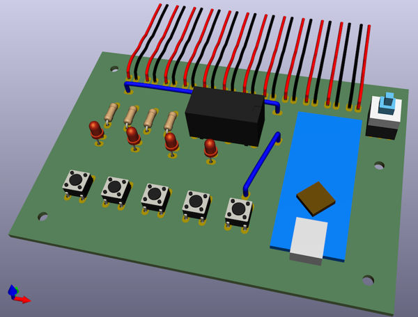
The two line LCD display on the drawing vs the four line is due to limitations on finding correct parts inside of the software. The two-line has the same pinout (I think) as the four line so that’s why I used it. When I built this the first time I didn’t know about the pinheader part and never went back to correct that (until now). But other than that does anyone see any issues with how it’s wired?
CHT Type IV Mk-VIIII_bb|690x463
I did some LCD displays a while back, maybe one of these is closer.
I retract these two statements:
I spent some time reading up on thermocouples, the amplifiers you want to use, and how it works. I think you are right on track on that part.
The LCD display you choose doesn’t really matter either. Sparkfun makes great products and they work. I guess my thoughts on the display was based on the cost. I use 2.8" TFT LCD displays with touchscreens for half the cost of that character display.
I still stick by my comment on power supply, maybe… What are you using this on? I get you are using it on a VW bus engine, but what is the engine in? A VW bus? Or something else?
Anyway, the electronics I would think you would be mounting inside of the passenger area, where you would have a good 12v power source to run any other electronics. A 5v regulator and a capicator will do the job.
Randy
Randy,
Yes it is going into a 1976 VW Camper Bus and as far as where it’s going to end up, I haven’t really given it much thought as i’m working on getting it working first then worry about that.
It looks good but to make life easier I would layout in KiCad it has so many more templates and components for you to use and the forum is very good for help fritz is ok for small board stuff
Good luck Bob
KiCAD doesn’t have a picture view like FZ, and it’s that picture view that you find in most automotive circuit diagrams in workshop manuals. KC’s 3D view isn’t really a substitute.
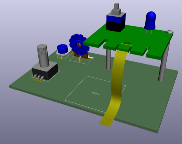
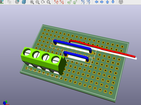
Well, Kicad does have a “picture” view of the PCB layout. It’s not the same as the Breadboard view in Fritzing but, still useful. And, the Parts making is very easy. It does take some time (call it 30 minutes) to get a good handle on it but, once learned… powerful.
Some screenshots attached…
Really you don’t need either, you can just draw it in a drawing program 
KC’s 3D view is more for positioning and clearances, ie, a 3D PCB render, where as FZ has a better teaching type layout that is similar to the layout in automotive workshop manuals. Basically what he’s doing doesn’t really require a drawing, so it’s probably to convey an idea, ie, learning. It’s just not the same.
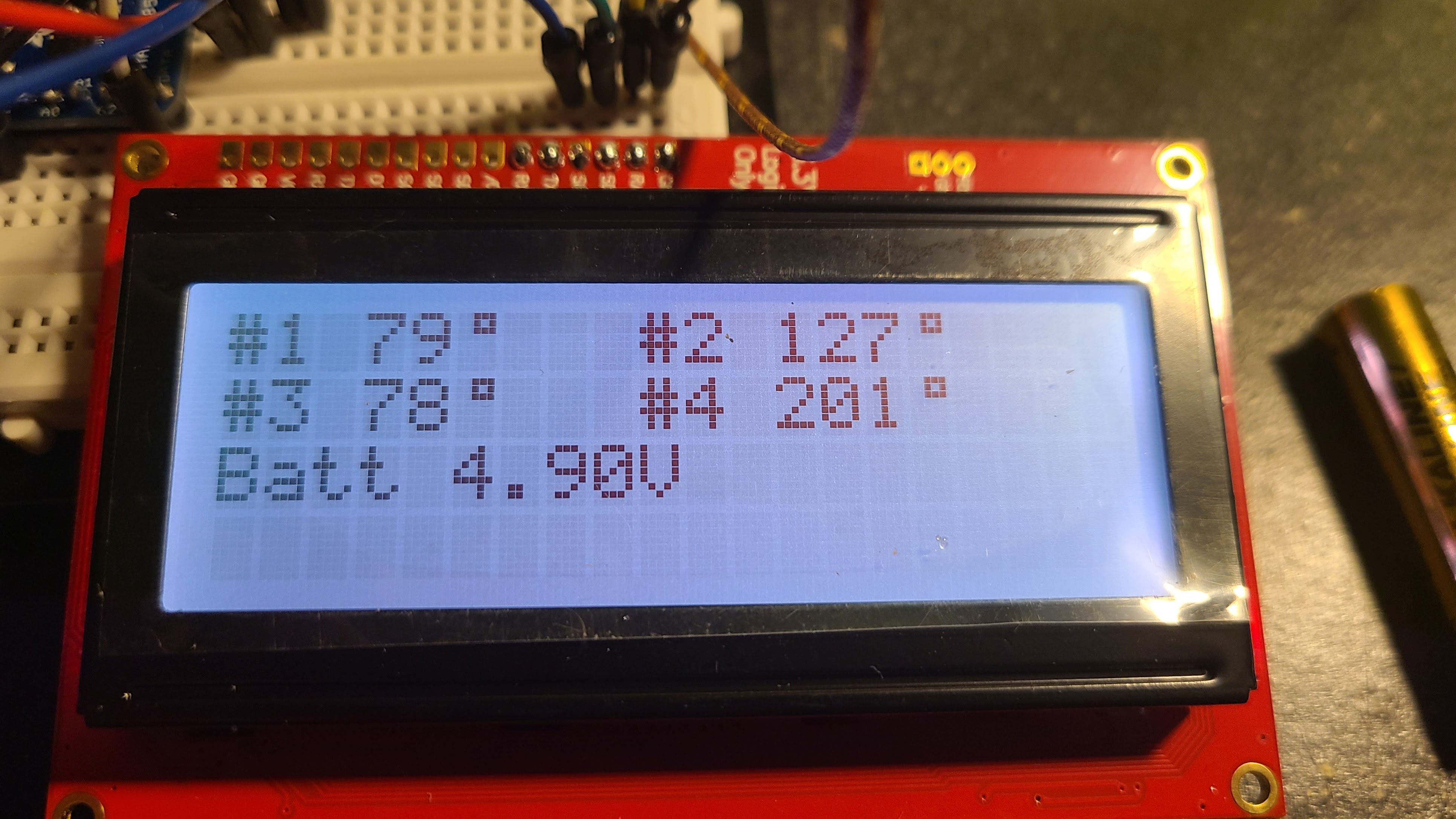
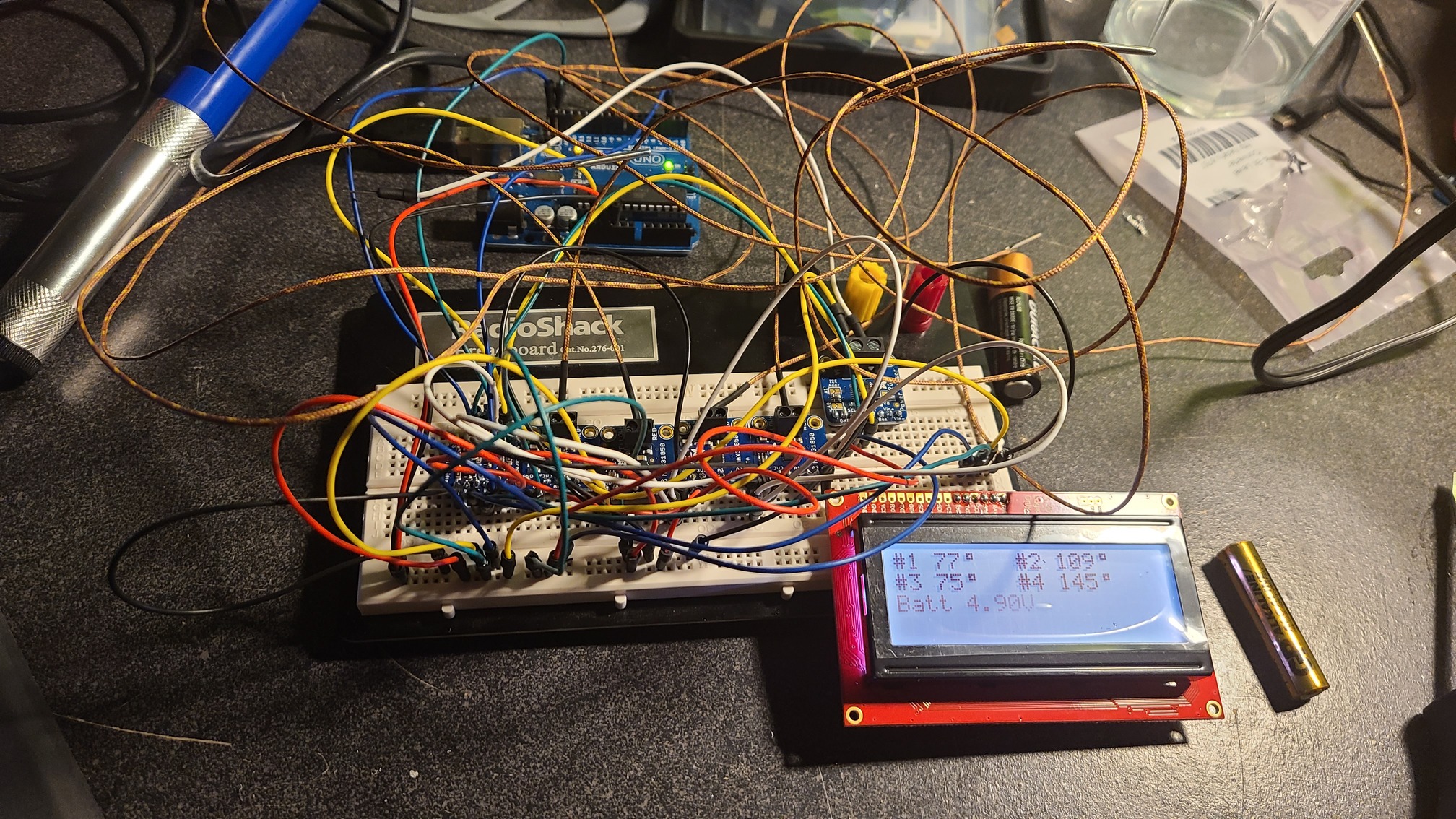
I’ve got it working!!! thanks everyone for your assistance with this. The issue was my soldering!
Requesting temperatures…Dallas Temperature IC Control Library Demo
Locating devices…Found 2 devices.
Parasite power is: OFF
Device 0 Address: 3B7EDF410BF40DE9
Device 1 Address: 3BBFDF410BF40D41
Device 0 Resolution: 12
Device 1 Resolution: 12
Requesting temperatures…DONE
Device Address: 3B7EDF410BF40DE9 Temp C: 12.25 Temp F: 54.05
Device Address: 3BBFDF410BF40D41 Temp C: 12.25 Temp F: 54.05
Both temps are from a cup of ice water
This project already has everything you need…
true but as I said earlier, I kinda want to design this and push myself to build it
Yeah you learn more if you do it all yourself, but for me I hate coding