Just started using this app. How do I add this switch to my parts?
https://www.microcenter.com/product/432084/nte-electronics-spdt-snap-action-long-hinge-lever-switch
Just started using this app. How do I add this switch to my parts?
https://www.microcenter.com/product/432084/nte-electronics-spdt-snap-action-long-hinge-lever-switch
If it isn’t in core parts (and it doesn’t appear to be) your choices are: use one of the spst switches as a substitute (which won’t look identical), do a google search for “fritzing part lever switch”
which turns up
where you would download the fzpz file and load it in to Fritzing (although it has an extra terminal), or make a new part or talk one of us in to doing so (as parts making is fairly complex.) I expect using the github part is you best bet as it is reasonably close.
Peter
This is what I needed. I am actually using a SPDT switch but only one side of it. This is for my garage door monitoring/home security project.
Thanks!
Hello
I am using this D2F-FL Omron switch in my project but I am concerned that in the PCB view it has a yellow border all around it. Does that mean that it’s conductive please? I would find that unusual but when I upload my board to the PCB manufacturer’s site it is looking like a trace? If it is it would short the contacts!
Could you please help put my mind at rest with regard to the nature of the border?
Thanks so much!
Your best bet is to upload the sketch (the .fzz file, upload is 7thicon from the left in the reply menu) as without the sketch to see what is potentially wrong it is hard to make any comment.
Peter
D2F_FL_Omron_Snap_Action_Limit_Switch_with_Level__83c59c313e2b62eaee4880a0febd4176.fzp (3.6 KB)
Hello Peter,
Of course, my apologies, please find the part attached.
Thank you for your help, as ever! Much appreciated.
To recap; the yellow border around the part in PCB view is causing me to doubt its accuracy. Is it conductive in your opinion please? I am unsure how to remove it if so…
That isn’t a complete part, only the fzp file. The part should be a .fzpz file which contains the .fzp and 3 or 4 svg files.
Peter
D2F-FL Omron Snap Action Limit Switch with Level (2).fzpz (5.5 KB)
I’m so sorry. Is the attached correct please? This is .fzpz.
Thanks for your persistence!
Best wishes.
That is the file I needed, and indeed it doesn’t look correct. I’ll post a corrected part in a bit.
Peter
Brilliant! I suspected something was wrong. Thank you. Best wishes.
OK here is a corrected part. The original had holes of size 0.028in (rather than the recommended 0.048in) and lacked a copper1 layer so it would only connect on the bottom of the board among other problems.
D2F-FL_Omron_Snap_Action_Limit_Switch.fzpz (4.1 KB)
This part has a new moduleId so it can be loaded beside the original part for comparison.
Peter
Hi,
Many thanks. The part works well in Fritzing. However, when I upload my design to Aisler I am afraid the PCB design does not match Fritzing as there is a strange anomalous component in its place.
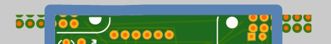
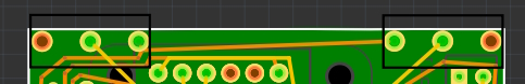
I have attached a section of a screenshot of both Aisler and Fritzing to demonstrate.
Could you please tell me what is happening here and how I may correct it?
Thanks so much!
The best bet is to upload the .fzz file for the sketch. As before the screen shots aren’t that useful to seeing what is wrong, I need the sketch to see what Fritzing does for me in terms of gerber output. If you haven’t you should also run DRC as some of the traces look to be too close together in the screenshot (which may or may not be true in real life!)
Peter