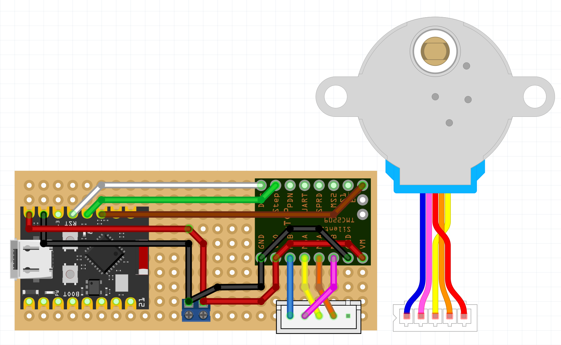
I’ve sketched out this little board for a project I’m working on to control my blinds at home. I wanted to learn a bit more about stepper motors and I have some TMC2209 around from my 3D printer modifications.
I can do the unipolar/bipolar modification for the 28BYJ. I’ll use ESPHome for the software, but I’m unsure about the stepper pinout. I have the 5V version of the stepper so the whole board should be running on 5V.
Questions I’m hoping someone kind and better experienced than me can answer:
Do I need to connect VIO and VM and the Ground Rails? I think this is motor power but I’m not sure if this is required if the voltages are the same.
If I need to connect them, do I need a cap across them?
Have I made any glaring errors?
If you have time to give me some pointers, I’d be delighted!
The best bet would be to upload the sketch (the .fzz file, upload is 7th icon from the left in the reply menu and accepts .fzz files.) It is currently unclear to me what driver you are using (it doesn’t appear to be the unl2003 driver from this post:
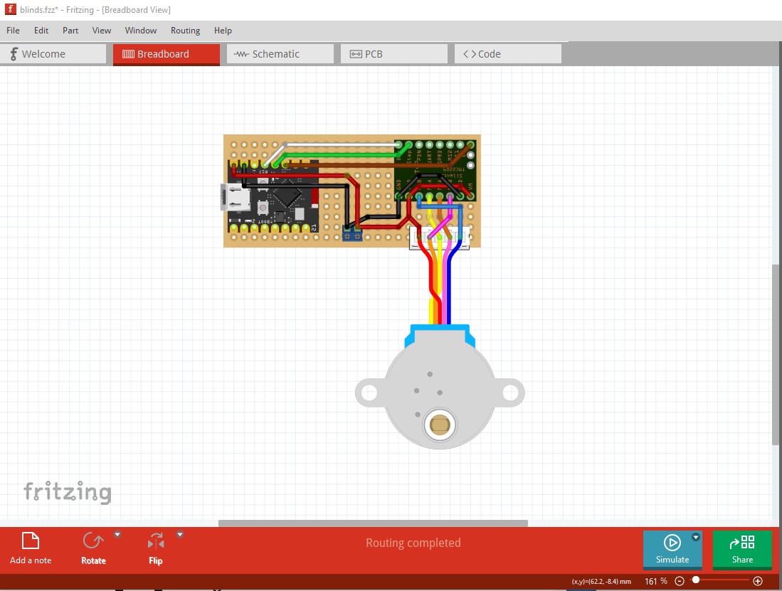
and it is therefore not possible to look at where the wires go which would be required to figure out much of anything. Assuming your parts are configured correctly (which they may not be) you should be able to drag the motor on the the connector for the motor driver which will populate the wires in schematic view and tell you (and us) what the connections are. Your sketch should allow me to make it do that (although I may have to modify the parts.)
Thanks for taking a look. Sorry, I’m just learning this fritzing stuff. It is not the ULN2003, it is the TMC22209. Indeed, it looks like you were the one who made it! I’ve attached the fuzz to this.
The .fzz file will contain all the parts not in core parts so you don’t need to include them. The added parts will appear in the temp parts bin. The .fzz should give me enough to comment further.
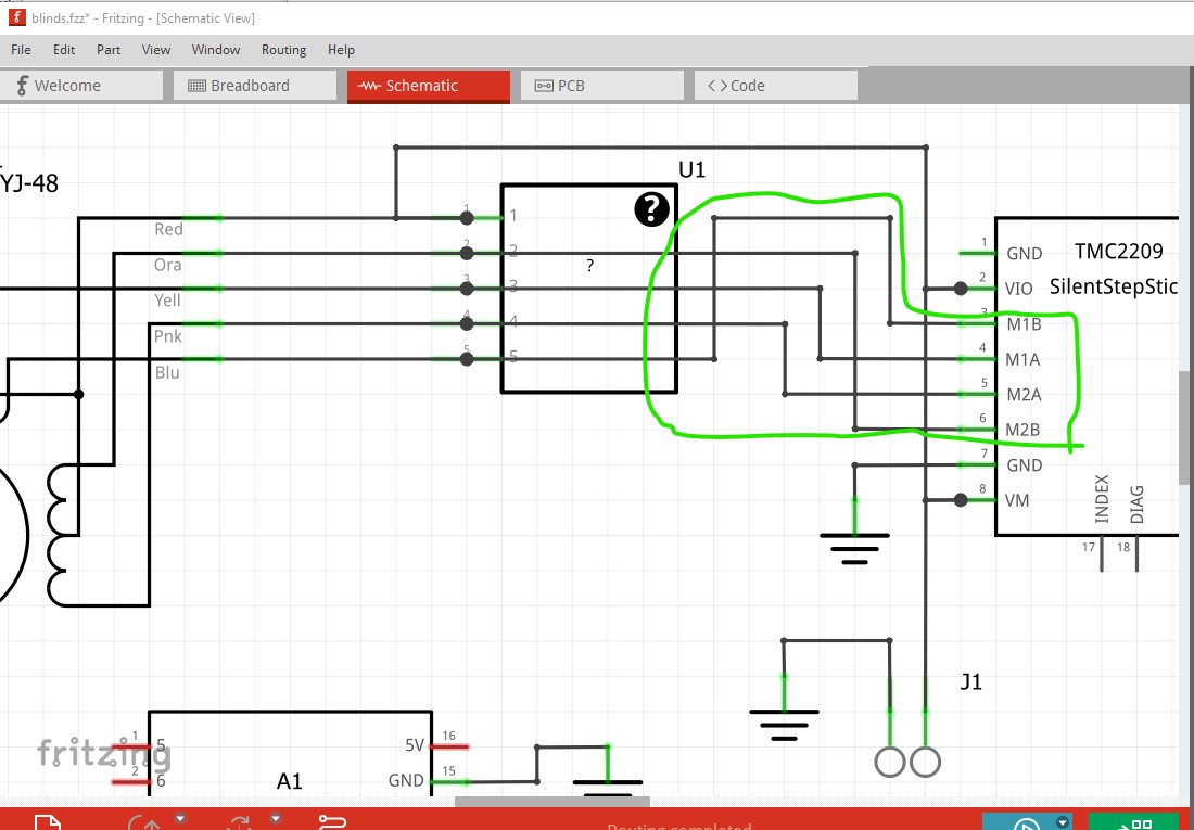
Basically the red wire connects to 5V (rather than a motor driver output) and the blue wire goes to one of the motor driver driver pins (it was previously unconnected.)
That may mean you need to change the order of the motor driver outputs to match what ever your software is doing to drive the motor (here I routed schematic view.)
Thanks Peter. I’m following the apparently well trodden path from here.
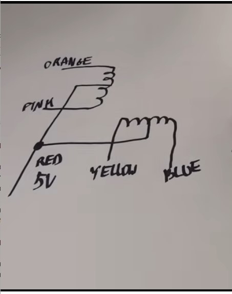
Your notes are correct for the unipolar design, for the bipolar I believe the common line (red) goes unused. That page shows a separate power supply for the motor (top right at the bottom of the page). My assumption is that if I am using 5V in that I need to bridge from VIO to VMOT and across the GNDs.
I’ll need to go rummage for a breadboard and some cables, mock it up and see. I was mostly worried about letting out the magic smoke on some of the components. I shall treat it as a learning curve and report back
It is worth routing schematic as that will catch wiring errors in breadboard (such as the red wire having a connection when it shouldn’t and the blue wire having no connection when it should have one. Wire breadboard then click on the rats nest lines (created from breadboard and pcb) in schematic and route them. Then check the schematic connections go where you expect. It is very easy to make mistakes in both breadboard and pcb, but routing schematic and checking the connections make sense will usually find them.