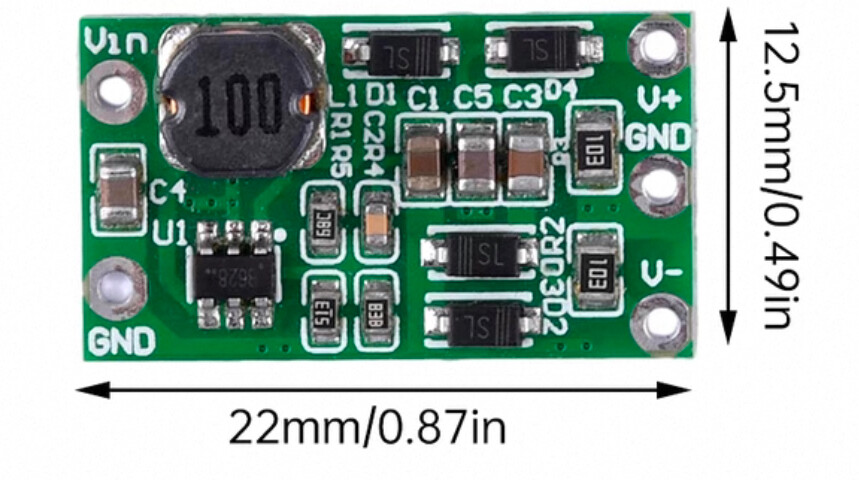
I’m working on a project that uses a small DC–DC boost converter module measuring 22 mm × 12.5 mm with the following pinout:
• Left side (input): VIN, GND
• Right side (output): VS+, VS–, GND
I’d like to create a fully functional custom part in Fritzing so that I can drag-and-drop this module in Breadboard, Schematic, and PCB views. My specific requirements are:
1. Breadboard View: a flat, top-down SVG showing the green PCB and white silkscreen labels exactly as on the real module.
2. Schematic View: a simple symbol with correctly named pins.
3. PCB View: an accurate footprint matching the module’s hole spacing and overall dimensions.
So far, I have:
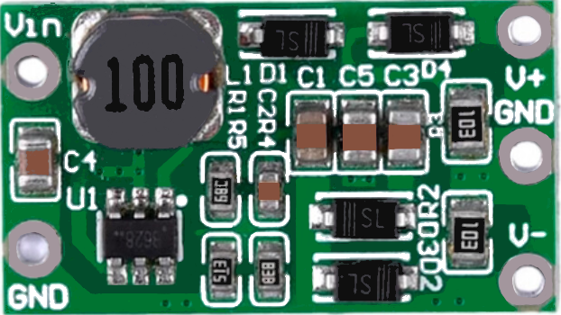
• A photograph and PCB layout for reference.
• Rough SVG drafts for a flat top view and for SMD component styles (capacitors and inductors).
What I need help with:
• Guidance on turning a PCB drawing or photo into the three required SVGs for Breadboard, Schematic, and PCB views.
• Instructions on defining connector IDs, names, and types in the Parts Editor.
• Any example SVGs or .fzpz files for similar boost-converter modules that I could adapt.
If you’ve created a similar custom part or have a template I can start from, I would greatly appreciate it. Please let me know if you need additional measurements, pin spacing, or images. Thank you in advance for your time and help!
Search for boost converter in the forum search bar. I made a bunch of these some years ago which are in the forums somewhere. These two tutorials for making parts apply to current Fritzing versions.
I lately learned there aren’t links to the videos in Old_Grey’s tutorial so you need to do a google search for the title and then they come up on YouTube.
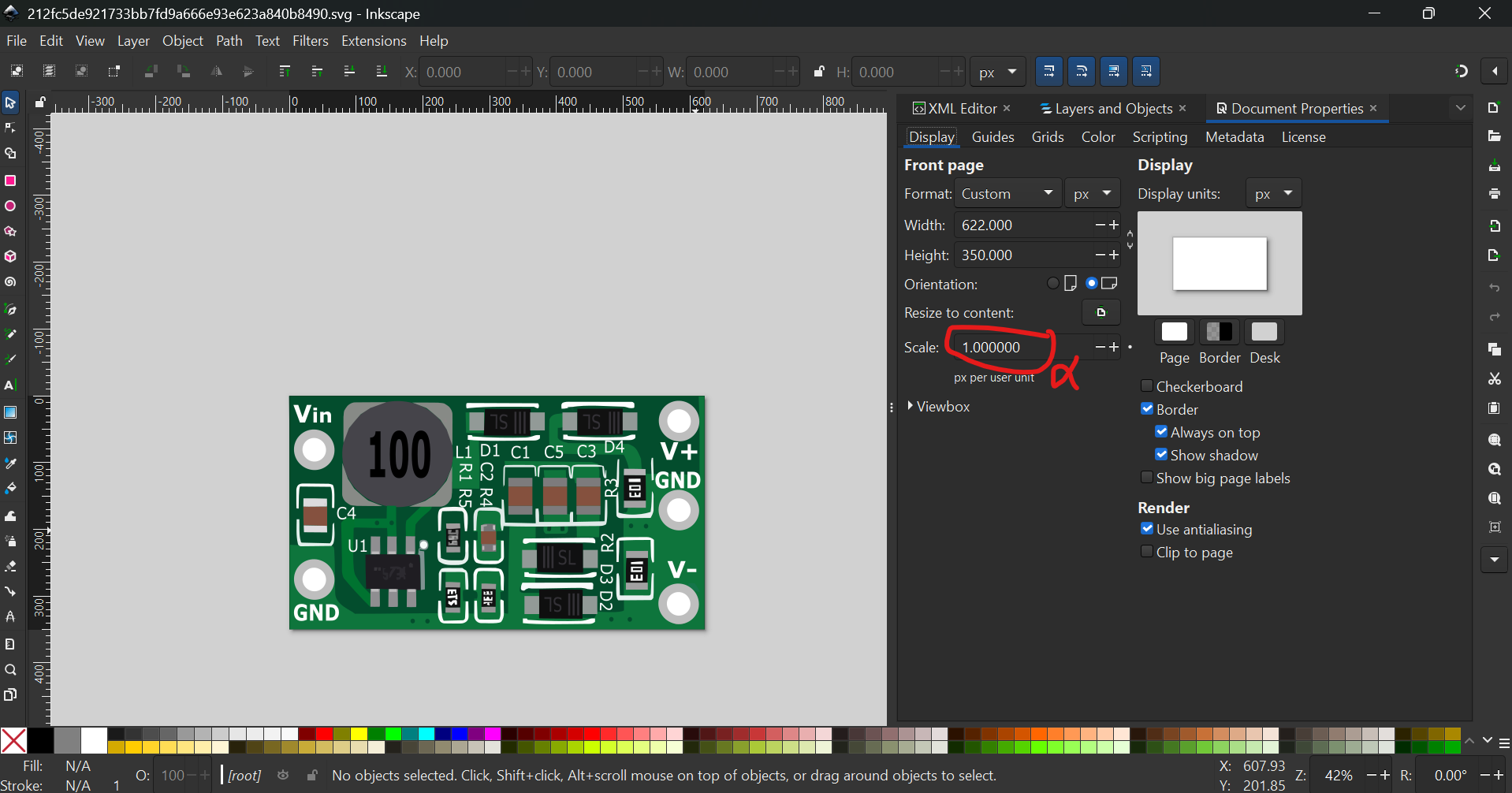
If you want to make a pretty part then you can make a png file from the board, like
This you can convert in one of the online converters to an svg file, which will be huge, in this case the produced svg was 1.5MB. Then the work begins, using Inkscape you replace the irregular shapes with regular shapes (circles, rectangles,text etc) and clean up tracks and not required shades.
This gives you a still large (88k) but manageable svg which you can use for your icon:
Certainly, but please be aware that this is not to scale anyway, it is just good enough for a pretty icon as is as I have not had the correct pin locations but just went for the picture.
The pins will still need to be located at the precise positions.
If you look at the picture you will notice that the vias are shown in an angle.
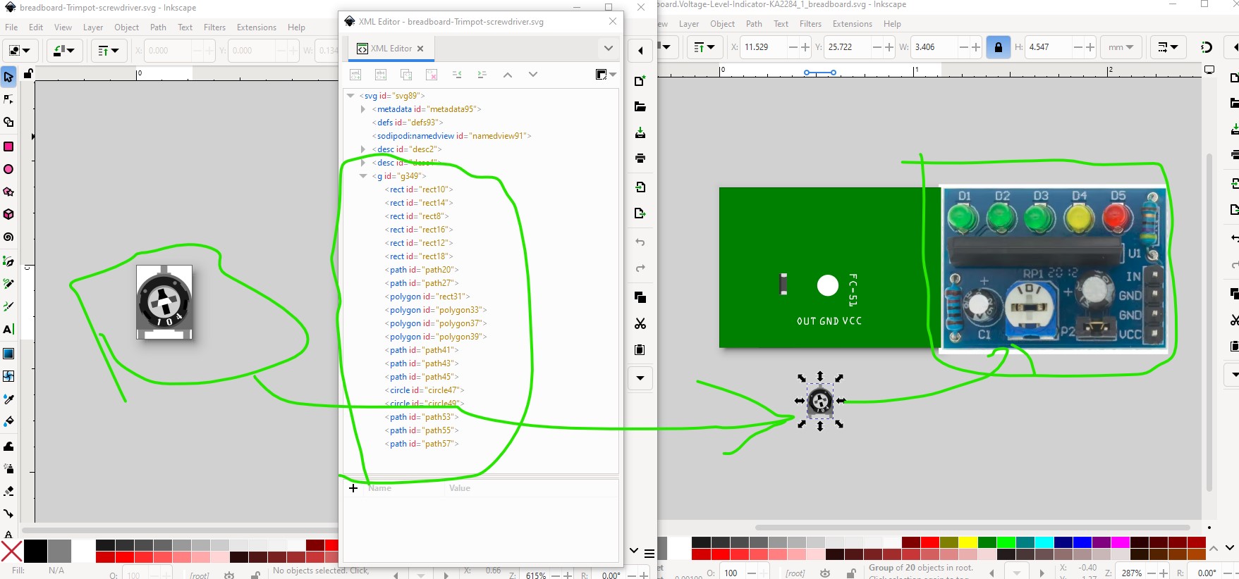
It is much easier to just create a svg from a collection of breadboard images of common parts and a template of the svg. I have a collection of svgs (usually parts with the connectors removed) for use in making breadboard svgs from a scaled image file of the part. Much easier than trying to process a converted inage to svg file.
It certainly easier. I appreciate all the help I have received from you and I certainly would not expect you to spend hours converting svg files on each part request. You would need to apply for getting 48h days and 10 of them per week.
But if someone wants to spend the time to make a part themselves then this can be an option to make it individual and easy to recognise, unlike in a huge array of similar looking parts.
Unless you want to make a lot of parts (in which case a svg collection is worthwhile, I suppose I should publish mine at some point, it isn’t a secret I am just too lazy ) my view is you are better off asking for a part here. Making parts (even with parts editor which I dislike, because it is not finished and has a lot of issues) is hard and takes a long time to learn (and tends to bite without warning leaving you with a non working part) and isn’t worth it unless you need a lot of parts (and have a lot of time, I am retired so my time is my own which helps a lot.)
It wasn’t completed when development stopped int 2016 so it has issues as it wasn’t completed. I believe there is a project ongoing to create a new parts editor but it hasn’t been released yet. I find editing the underlying files much easier (although that requires you to understand the xml sufficiently to do so which is a non trivial task in itself as it is mostly undocumented.) If you post a data sheet for the part you want I can make it without problem.
Since I happen to be making a part for someone here is an example of what I mean. The svg on the right is my breadboard template file with a few common things in it. The image on the right is a scaled jpg or other image of the part that will fit over the green board (after it is set to the correct blue color) and allow the components to be placed. The pot was selected from my part collection (which is a pot from core parts with the connectors removed copied in to Inkscape.) It needs to be scaled up a bit to be the correct size and the other parts added (including a generic 4 pin and 2 pin male header that do have connectors!) the capacitors and LEDs and the whole thing comes together fairly easily.