@GummiQ Hello and welcome to the forum!
microMerlin’s right, there is no easy way to do this, but it can be done. It’s a matter of how much time you want to spend to get the results you want.
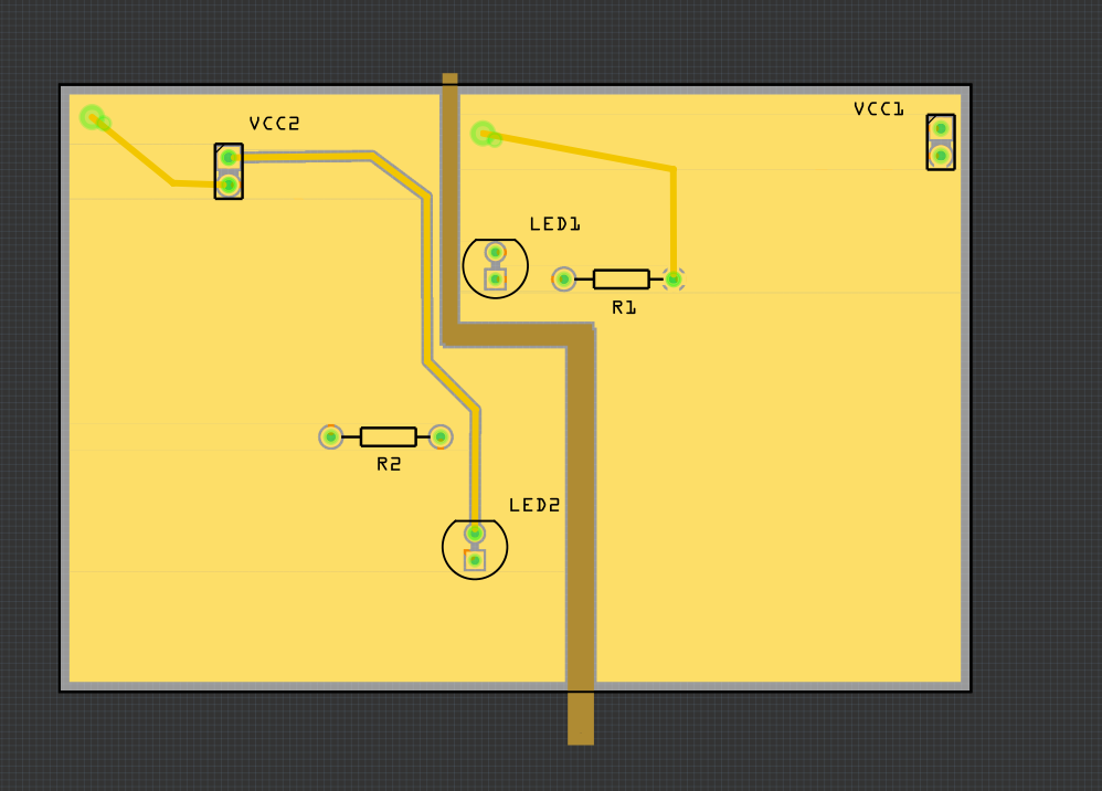
Here I have 2 different power sources, each one connected to a resistor and an LED. I added In copper blockers (the vertical-horizontal-vertical brown line) to separate the two sides of the board. Set both power sources (the 2 pin headers) positive pins to be the ground fill seed, and then added in the ground fill on the top side only.
Here’s the file:
groundFill_ex1.fzz (13.8 KB)
Understand, in Fritzing, copper fills have no connections, only ground fills can be connected to a part. This is why I selected the + power connectors to be the seed for the ground fill, then did a ground fill. The ground fill is now a + voltage copper fill.
Look, unless you are moving so much current that you can’t use a wide PCB trace, don’t mess with the copper fill. I’ve had mixed results with it…
Good luck,
Randy