Hi all,
I want to create a small opto-coupler project to exchange digital I/O’s between a PLC and Arduino.
For that, I want to have 2 different “ground” cupper fillings at the buttom side.
One half for 24V, other half for 5V, separated by a unfilled area.
I’m not able to create two seperated areas on the same PCB.
Am I to stupid, or is there no (easy) way to do so?
Wer kann, kann mir gerne in deutsch antworten, macht mein Leben einfacher 
Gruß aus NRW
GummiQ
There is no easy way to create separated, isolated ground fill areas on the same side of a board in Fritzing. You might be able to implement, depending on the rest of the PCB trace requirements, by adding and routing traces such that the fill on the separate halves of the board can not ‘flood’ from one half to the other. Creating 2 ground ‘islands’.
@GummiQ Hello and welcome to the forum!
microMerlin’s right, there is no easy way to do this, but it can be done. It’s a matter of how much time you want to spend to get the results you want.
Here I have 2 different power sources, each one connected to a resistor and an LED. I added In copper blockers (the vertical-horizontal-vertical brown line) to separate the two sides of the board. Set both power sources (the 2 pin headers) positive pins to be the ground fill seed, and then added in the ground fill on the top side only.
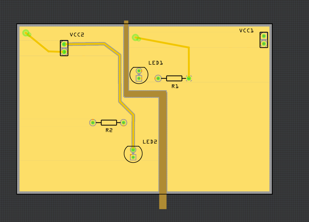
Here’s the file:
groundFill_ex1.fzz (13.8 KB)
Understand, in Fritzing, copper fills have no connections, only ground fills can be connected to a part. This is why I selected the + power connectors to be the seed for the ground fill, then did a ground fill. The ground fill is now a + voltage copper fill.
Look, unless you are moving so much current that you can’t use a wide PCB trace, don’t mess with the copper fill. I’ve had mixed results with it…
Good luck,
Randy