I need to drive an 1mA through a resistance which can vary between 5k and 50K ohms over less than 10mS (so it needs to adjust very quickly to these resistance changes).
The actual current value need not be very accurate - 1mA +/- 10% - but it must be stable because it is the reference current in a four-electrode resistance measuring system.
I’d done that search and I think I’ve understood how the circuits work. But - please excuse me if I’ve misunderstood - the constant current circuits I’ve been finding are intended to drive eg 1mA through much lower resistances and thus with much lower voltages behind them. I’ve been concerned specifically that these designs would not give the stability or deal with the high voltage (up to 50V) I expect to need.
It’s a matter of choosing the right kinds of components so the circuit can handle what I think are slightly unusual requirements.
The transistor constant current source in this page should do what you want. As long as the transistor involved has a > 50V Vce rating it should work fine. There are likely power supply IC circuits that produce constant current that would do the same job although I am not immediately aware of any examples.
Your helpful suggestion solved my immediate problem. I’ve gone, initially, with the simple design using the Zener diode and transistor. Now I want to look at improvements.
The system I’m building switches polarity at 128Hz (the precise frequency isn’t important - anywhere from 60-130 Hz would be fine, avoiding main supply frequency and sub/multiples).
Thus what I’m driving into the varying resistance is actually a square-wave with a constant current, positive or negative, at each half-cycle. My solution at present is to generate a constant current and then switch it using a set of solid-state relays driven by two pins of an Arduino (an Arduino rather than a 555, for example, for flexibility). When one pin goes high one pair of relays switch on and divert the positive and negative outputs of my constant current source to the electrodes connected to my varying resistance. After 1/64th of a second the Arduino pin goes low and another pin goes high, switching on another pair of relays which divert the same constant current source positive and negative to the opposite connections of my varying resistance thus reversing the polarity of the voltage and the direction of the constant current.
With this arrangement the current is not actually constant. It has to catch-up on each half-cycle after the reversed polarity. I therefore need the fastest components I can use (suggestions welcome for an appropriate, really fast BJT transistor - since I suspect this is the slowest component which therefore determines the current rise-time at each half-cycle).
But I’m concerned that the whole circuit is rather clumsy because of the mechanical way of generating a constant-current square-wave through my resistance. In particular I’m generating a square wave by switching relays (albeit solid-state relays) at 128Hz. Thus their expected life of about 50-500 million operations is going to get used up pretty quickly - of the order of 100 days of continuous use. That’s not a lot.
Can anyone suggest an alternative way of generating such a constant-current square wave given my parameters (higher up the thread)?
Don’t you need a H-bridge rather than relays? Reversing the current direction is normally what is achieved with H-bridges. Of course you can do it with relays too, but as you say, doing it at high frequencies won’t be good for their life expectancy.
You can build a H-bridge with MOSFETS yourself or use a H-bridge chip for it. The L298 from ST Micro is a popular H-bridge.
This isn’t actually correct and faster components won’t do anything about the rise/fall times. The constant current source will provide constant current (varying the voltage to keep the current constant.) The rise/fall times are likely due to the capacitance of your electrodes. With a constant current source you will get a triangle wave (not a square wave) output, as the constant current source will charge the electrode capacitance with the same current making the voltage rise at a constant rate. The same effect occurs when driving power MOSFETs (where rise time is important for power dissipation reasons) and the solution there is to have either a high current driver that will charge the gate capacitance fast or a similar size to gate capacitance capacitor in series with the gate to quickly charge the gate capacitance with a high current to make the transition time quicker. This is incompatible with your desire for a constant current output. You can have either fast rise time but not constant current or (with constant current) a linear (depending on the electrode capacitance and charge current) triangle wave with slow rise time. As to the driver I agree with @dmantione an mosfet h bridge driver (driven from your constant current source) is likely the best answer.
In fact, when I came to compare them, the system I’ve built is topologically equivalent to an H-Bridge but instead of using four transistors I’ve used four relays. My variable resistive load takes the place of the motor in the Arduino example.
I’ll need a bridge capable of handling higher voltages than the max 35V of this example but I should be able to work that out.
At 1Ma and a low frequency it should be easy to make an H bridge from mosfets (which like transistor can have high source drain voltage ratings.) The typical problems with high power H bridges (the potential to short if both bridge mosfets are on drawing excessive current and causing failure) isn’t a concern with a 1Ma constant current. That should eliminate any duty cycle concern with the relays, as far as I know Mosfets don’t have a limitation other than possibly age on how often they are switched (although I’m not particularly an expert on this either!)
edit:
For simulation a spice model of the circuit (which would require knowing the various characteristics of your electrodes such as capacitance) would likely give illuminating results. I know very little about spice simulation other than it is possible to do for AC circuits which is what you have.
For clarity (and perhaps for interest as well): The device I’m intending to build will measure the electrical resistance of the soil using the standard four-electrode arrangement. Two electrodes put a (predetermined or measured) current into the soil and two others measure the potential difference this produces to calculate an “apparent resistance” value using Ohms law and a geometric factor to deal with the electrode positions. The concept of electrical resistance in soil is not simple - there’s a degree of capacitance, as you say, and (a little) inductance from a variety of physical-chemical effects the spatial distribution of which is immensely complex and varied.
So when I say I want fast components I’m aware that the capacitance at the electrodes will slow things down - and I want fast components elsewhere so that when I measure the time it take for the voltage to rise in the soil (so I can explore the soil physical chemistry which determines this “soil capacitance” rise-time) I can discount the rise time of the other parts of the circuit, as far as possible. Typical rise-times for soil-electrode systems like this are a few mS, depending very much on the soil and the electrode configuration, so it would be helpful if the rest of the components do their job in nS to a mS or so. It’s not critical. For the simple purpose of measuring the DC soil electrical resistance I can manage without knowing the rise-time of the soil electrode capacitance but it might be helpful if I can make it possible to measure the complex impedance of the soil (which determines the rise-time) by design from the beginning (as some of the more sophisticated commercial soil electrical resistance instrument do).
I started out my thinking with the simple brute-force approach using a 40v supply into two electrodes in the soil and a shunt and an ADC to measure the current this produces, as well as the potential difference created by this 40v through the soil nearby. I then realised that it might be easier if I controlled the current instead so I didn’t need to measure it. But it can’t be a simple constant DC current because of polarisation at the soil-electrode contact. It needs to be switching polarity every so often so my intention has been to create a constant current and simply switch its polarity back and forth - and that’s what the relay-based version achieved. Geological ER systems use frequencies as low as 1Hz or less because of the time it takes for a stable current to get established in the ground over distances and depths of kilometres (and they use reed relays to do so to handle the much higher voltages they use). Typical instruments to measure building earthing (such as the various Megger earth resistance instruments) work by periodically reversing a constant current, thus creating as a square-wave at frequencies in the 50-150 Hz range. And that’s what I’m trying to achieve.
As a dumb soil physicist I have no reason to know the various parameters and capabilities of electronic components so this is a very interesting journey - and the advice I’m finding here, and the reading I’m being prompted to undertake, is much appreciated.
As I understand your last remarks, however, I won’t be able in any simple way to achieve the square, constant current (constant at each half-cycle, obviously) waveform I’d intended using a Mosfet H-bridge and I’d have to go back to my clumsy solution using solid state relays.
Which remarks? To me, Peter looks positive about the MOSFET solution and I do not see any problem with it either. MOSFETs will have a lower capacity than electrodes, so switching should be faster.
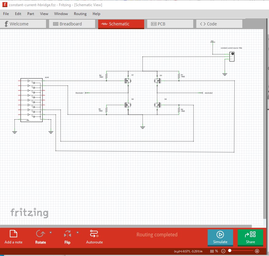
a circuit like this should work (you would be best to collaborate with a real electrical engineer to get the circuit right though!) The Arduino drives the inputs to the driver (which needs to translate the logic levels to ~70V for the high side of the h bridge) a standard hbridge driver IC would work as well. Essentially the two states are Q1 off Q2 on Q3 on Q4 off which puts electrode1 at ground and Electorde2 at ~70V. Reversing the state to Q1on Q2 off Q3 off Q4 on reverses the polarity. The constant current on the 70V means the usual problem of both Q1 and Q2 being on at the same time causing a short isn’t important. The 1ma current limit on the CC supply makes that a non issue. All that said I assume you are aware the there are commercial versions of this device available (I don’t know if they have constant current outputs or not as there isn’t much technical information available.) I have made Fritzing parts for a number of them I think at least one with 4 probes. Here is a recently modified 3 probe version
That comment isn’t about the H-bridge (which will work fine) but about the fact that a constant current source driving a capacitance will have a linear rise time set by the time constant of the RC circuit made by the constant current output and the electrode capacitance. The common way to turn a square wave in to a triangle wave (with a linear rise time) is to feed the a constant current in to an op amp integrator. That is essentially what the electrode capacitance (and I have no idea of what that capacitance is, so it may or may not be an issue) will potentially limit your rise time no matter how you drive it. The only thing that would change the rise time is to increase the current charging the electrode capacitance. That may be why they measure the currents, having a higher current will enable a faster rise time. Of course you need to balance higher current (along with high voltage) as a human safety issue as well. A high voltage and high (ish) current source can be a threat to human life if the human touches the probe. Issues like this are why it would be best to consult an engineer who is familiar with the issues (and that by and large is not me!) and/or use a commercial probe.
Interestingly I’m not aware of any commercial versions available of the instrument I’m intending to build - though I own several different sorts of 4-electrode resistance meters of various vintages. In fact as far as I’m aware the only commercial instrument ever made which resembles that I’m aiming for is the Geoscan RM4 and Roger Walker who made these retired a few years ago (and the RM4 went out of production in the early 90’s, I believe). My French colleagues made an excellent instrument but have not commercialised it for sale.
The earth resistance instruments made by Megger, Fluke and others measure over a period of several seconds and present a mean value. They aren’t really useful as analytical instruments to explore the electrical behaviour of soils in more detail (though they do, of course, do the job they are designed for supremely well).
Geological survey instruments like my trusty Syscal ProSwitch72 (Syscal Pro Switch) are wonderful - but immensely powerful, bulky and expensive. They aren’t very adaptable either though they measure soil electrical behaviour very precisely. They are probably the best analytical instruments currently available for serious scientific work and mine’s in constant use in the field and lab.
The “NPK Soil Sensor” to which you refer is an oddball. It resembles the excellent WET sensor made by Delta-T of which I guess it’s a Chinese clone. This is an FDR and thus works on an entirely different principle. The “NPK” bit is definitely in brackets because an FDR can’t measure these ions - just the soil conductivity they and all the other soil solution ions produce by signal loss, as in any other FDR (or indeed a four-electrode galvanic system). I actually have been given one of the “NPK” instruments to have a look at recently but haven’t had time to do so.