Hello,
I have an arduino starter kit and it comes with this timmer potentiometer (V10). I believe the V10 trimmer potentiometer is the part used in the arduino starter kit: https://www.arduino.cc/documents/datasheets/Potentiometer.PDF?_gl=13cxwus_gaMjU4NDA5MjcuMTY0NDE2MDI3NA%E2%80%A6_ga_NEXN8H46L5*MTY0NTE0MTk1NS42LjEuMTY0NTE0MjAwNS4w
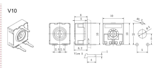
The spacing between the 2 back legs is 5mm and the spacing between the front leg and the 2 back legs is 10mm. I see there are timmer potentiometers in Fritzing but they have 5mm spacing between the front and back legs not 10mm.
I found pot-arduino-starter-kit.fzpz from CA9 9mm Carbon Potentiometer Part File (Arduino Starter Kit) - #4 by vanepp but the connectors and spacing on that part do not match the connectors on the physical part I have.
How do I change this spacing using the part editor? I’m trying to create a custom arduino shield so I only care that distances are shown on the PCB view are correct. I don’t care about the look.
Thanks!