100W 10A POWER BOOSTER STEP UP VOLTAJ YÜKSELTİCİ.fzpz (13.7 KB)
There is some error but I think it is not very important.
A few problems, starting with a Fritzing bug in Windows which means Windows won’t load the file name above, so I shortened the name to fix that.
Breadboard:
Has no layerId and thus won’t export as an svg.
The pot has connectors which it shouldn’t so replace it with a pot that doesn’t have connectors. Group the result and add a layerId of breadboard.
Schematic
created a schematic from the schematic template here:
fzp file
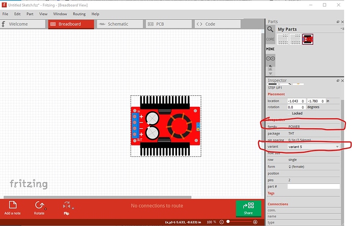
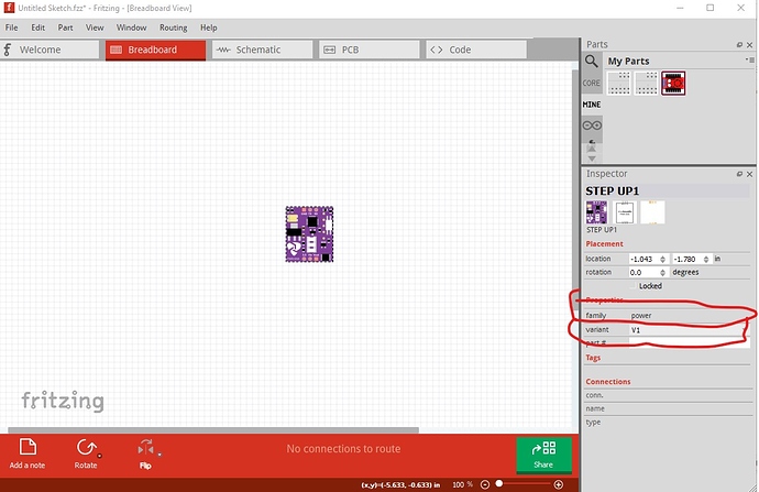
Change family to POWER Booster from power to make it unique to avoid this:
note the pull down menu on variant. If I select the V1 variant I get a completely different part (because the family is the same) which isn’t correct.
Suppress pcb view (instructions here)
renumbered the connectors and removed the unused ones (which is what was causing the red squares)
added a bus for the two ground pins. All of that results in this part
100W 10A POWER BOOSTER STEP UP VOLTA.fzpz (7.8 KB)
which works properly.
Peter

