PCB view BLANK after closing fritzing (1.0.6) and re-opening. I had edited and tried to print.
Steps I took that resulted in the problem:
Edit file. (created in 1.0.4).
Attempt to print. Fails. Output was ‘blank’.
Close fritzing.
Re-open fritzing.
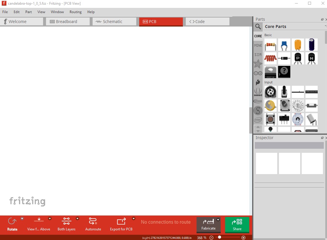
Load file. PCB view blank. Ah, well….
What I expected should have happened instead:
Well, that parts placed (holes, silkscreen) be present.
My version of Fritzing and my operating system:
This was my first attempt to use 1.0.6 in production.
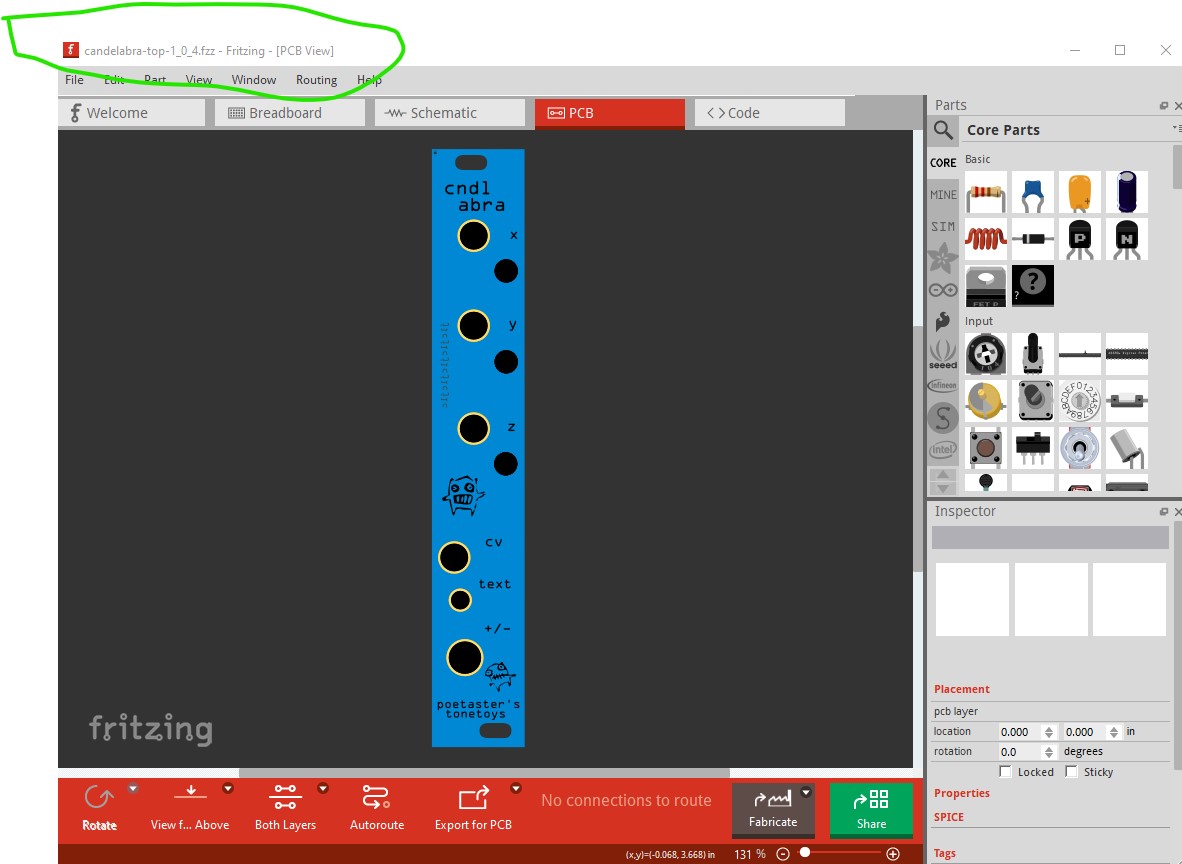
After that fiasco, I did a git restore of the file and opened the file in fritzing 1.0.4 which has been stable.
I did the edits (AGAIN, pay me by the hour!) Printed. That worked. Printing worked. Files were not corrupted.
Long story short, I did the same with 4 different fritzing projects and they are now in production at JLC.
I’ll try to make a report in the git repos, but at this rate I’ll probably just fork 1.0.4 and backport the changes myself. It’s WAY too scary for people like me who actually produce boards regularly to have the tool go south.
Can you upload the non corrupted sketch? Then one of us can try it and see if the problem is reproducible or something specific to your setup. I’ve been using 1.0.6 without seeing any problems, but I haven’t tried printing a pcb yet either. Upload is 7th icon from the left in the reply menu and accepts .fzz (sketch) files.
I did do another ‘run’ at it with a similar sketch (also only holes and silkscreen) since I thought it might have to do with it being only holes and silkscreen. Same result.
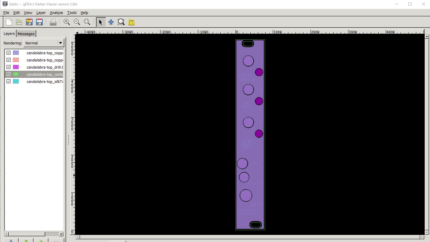
For me (without changes) it seems to export fine to gerbers. When you say print do you mean export to gerbers or one of the other print options? This is the gerber output displayed by gerbv on Fritzing 1.0.6. What kind of a change did you make when it broke, as it may be the change which is causing the problem?
I had done changes to the layout in 1.0.6. I tried to print them to the printer. It produced a blank piece of paper. The design, board & holes and silkscreen in this case where visible. After saving and closing and re-opening, the design was blank, just as the print had been.
That happened twice with two different files. What both had in common was being just board, holes and silkscreen.
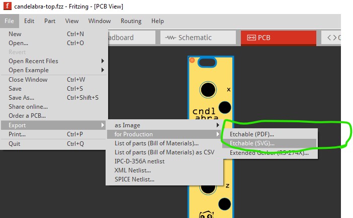
or one of the etchables (although I think these produce files rather than go to the printer.) Since that looks to be correct (it asks for a file name), I tried the first print command and it printed the image to my printer correctly and the image is still in pcb view. So it may be the change that causes the problem, or something is different on your system. If you can tell me what you changed I can try and do that and see if it will destroy the pcb view in Fritzing for me.
I am trying to reproduce what you did and see if it fails for me as well. In order to fix what ever is going wrong we need to be able to dependably reproduce it. My first guess would be disk space problems for temp files, Fritizing has had problems in the past with not checking return codes and things like a write failure to a file being ignored (which would usually cause the loss of the file.) It may also be a bug related to printing but to fix it we need to be able to reproduce it. It may be I also need to know what change you made before the failure happened, the bug may be in the change that is occurring and if so we need to be able to reproduce that too.
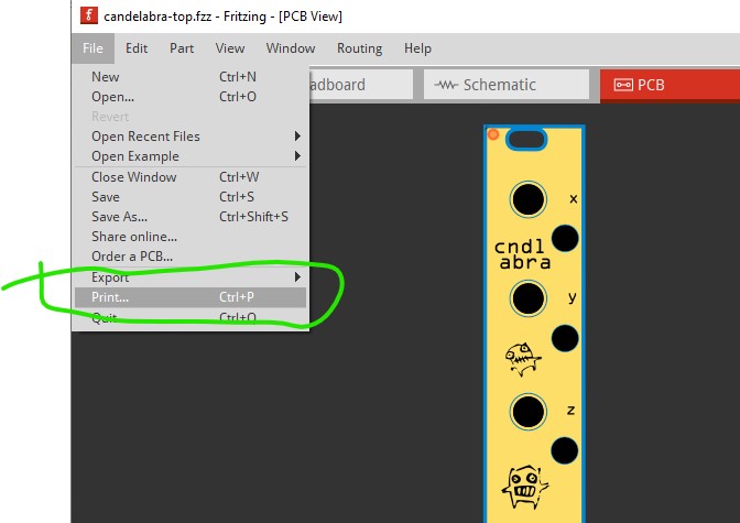
Ok, I made numerous changes and it was CTRL-P that I used to try to print.
The changes were all space related ( all holes up 6-7 mm) and placement.
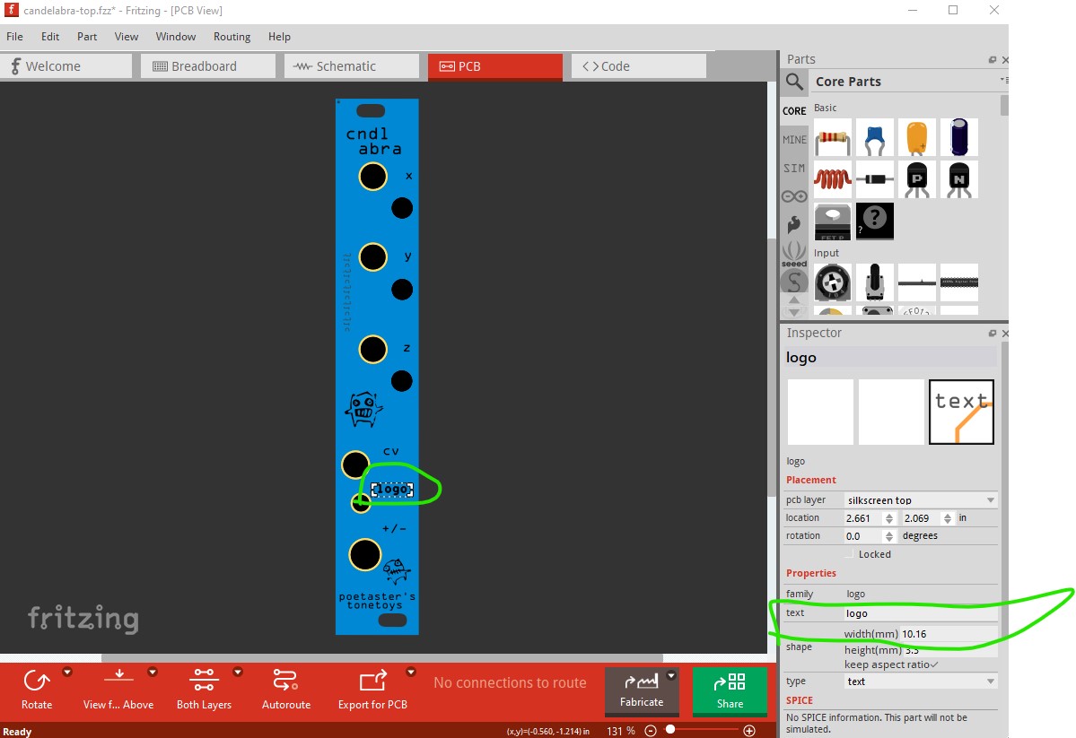
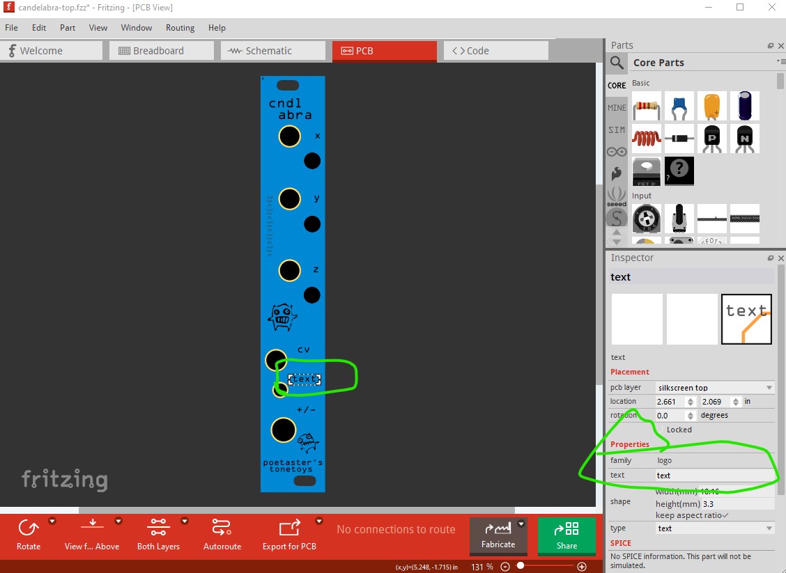
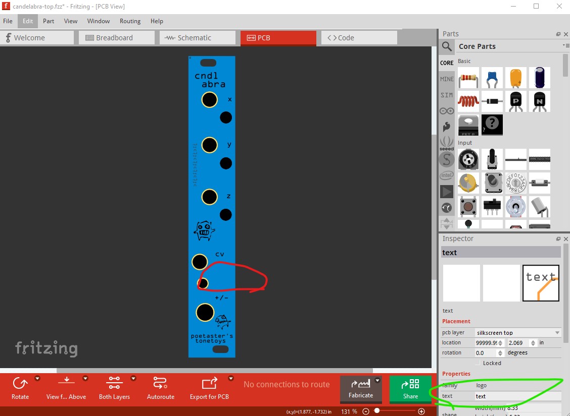
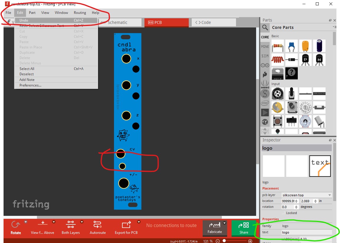
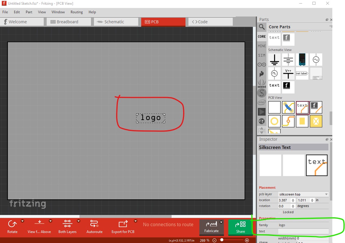
There was something odd with one of the texts. The text (>/>>) had been replaced by the word ‘logo’ which refused to be edited. The text just disappeared. So I removed it and copied the ‘cv’ text to replace it. Perhaps it was a corrupt element?
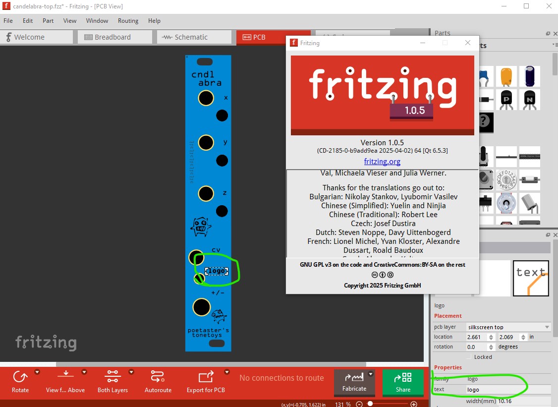
Just to be sure, I fished the commit out of git containing that version. When I open it (in 1.0.4) the text has been replaced by the word logo:
Ah, interesting. I didn’t have the 1.0.5 step in my work, since I’ve never used 1.0.5. So, the bug must alread exist in 1.0.4. Hmmm. but it is progress!
Debug logs (I tested with 1.0.6 ) show that Fritzing warns about “bad width and/or bad height in svg” when loading candelabra-top.fzz .
Specifically it warns about the svg for the empty “logo” text.
It is stored in the fzz with <svg height=".13in" viewBox="0 0 0 13" width="0in" xmlns="http://www.w3.org/2000/svg">
Omitting the leading zero is often understood, completely fine to use in some svg elements, like svg path. I didn’t yet lookup if it is allowed in the svg width.
But it is not how Fritzing would typically store these, all the other text start with a leading zero, for example height="0.0890258in" .
In theory we could just handle .13in as 0.13in , but I really wonder how this format got there.
A text like (>/>>) can be tricky to handle in xml, so Fritzing or any 3rd party tool could have messed that up. I could not yet reproduce any problems by entering >/>> or similar, it gets escaped as it should.
This is ‘just’ speculation, but I believe the odd text behavior occurred after I had first installed 1.0.6, It’s just coincidence, but I had installed 1.0.6 and begun rework the above pcb in 1.0.6 which led to this issue. However, I’m pretty certain the text/logo was an issue after I restored from git and edited with 1.0.4. Not that it led to a blank PCB view, but that trying to undo the text edit led to the item disappearing. So something about the element was an issue in 1.0.4 already.
Is that possibly a result of having resized the text box beyond bounds? In any case, it was a ‘plain’ text object like the others in the sketch. I did not edit the xml by hand.
Assuming <![CDATA[ ]]> and no bugs in the parser should be fine.
Indeed 1.0.4 with the debug log on makes the same complaint but loads the image with the text logo in it even though it appears the text in the xml is blank (from the debug log, although that may be another instance of the logo part.) I expect the issue is how the logo got stored wrong if it was all changed in Fritzing (rather than by a manual edit.) Doing so certainly breaks 1.0.6 as it deletes the pcb view entirely when the fzz is saved.
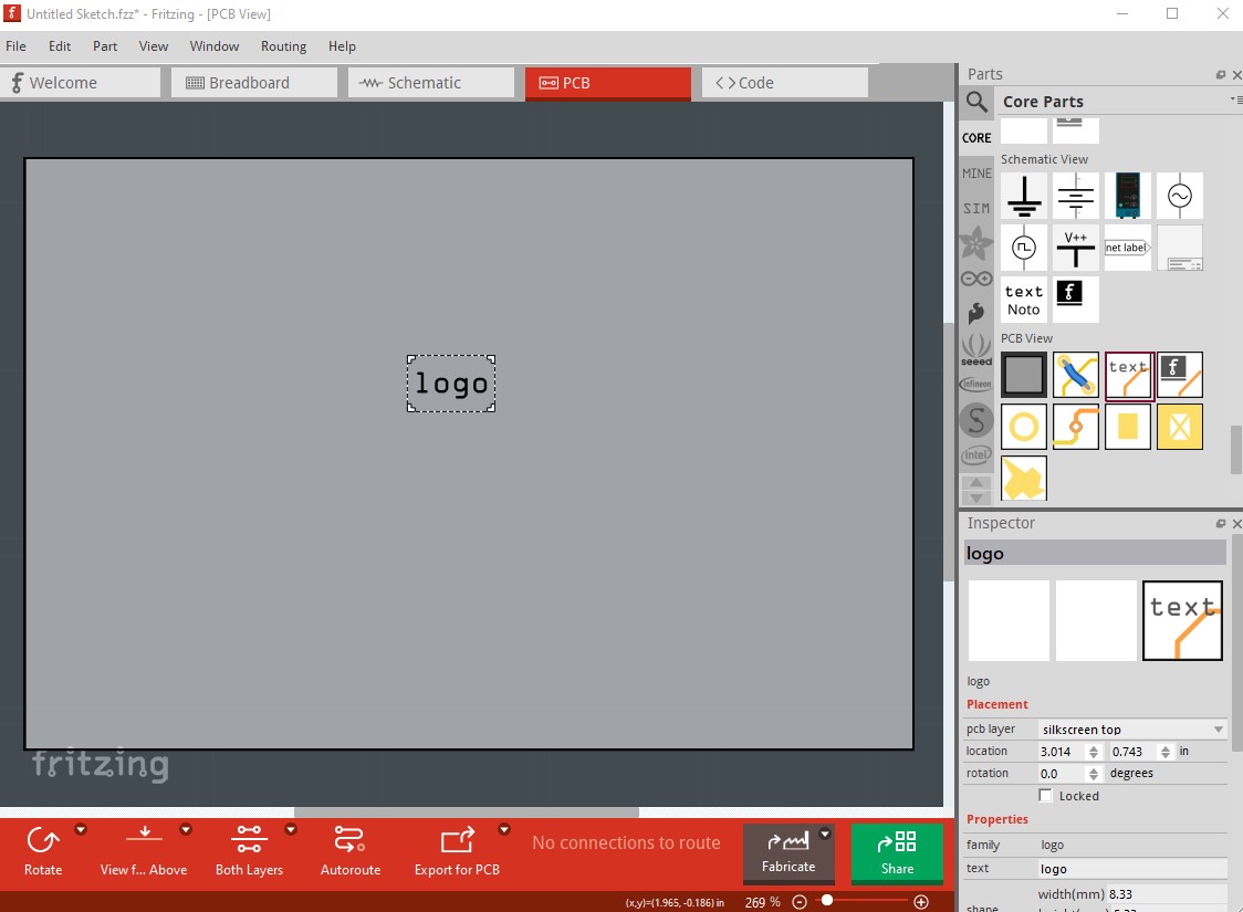
The svg appears to load successfully with no complaints in debug log, so I expect that should be fine. Even if it didn’t load correctly I wouldn’t expect it to change the text in the logo part. I just uncompressed the .fzz file and checked the .fz file. It looks to be unhappy with this entry
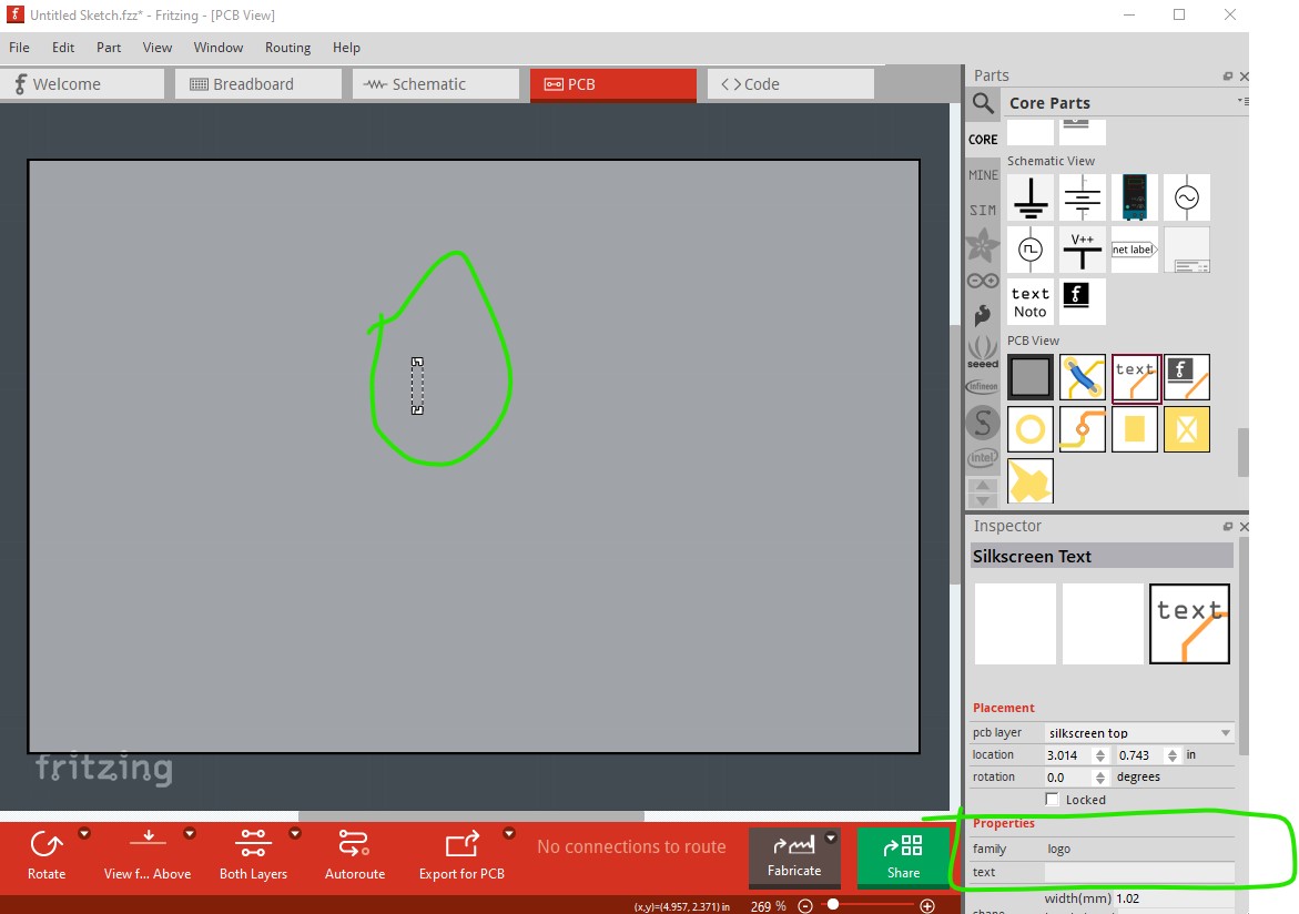
which appears to be a logo with blank text. Fritzing will let me create such a logo so let me save it and see if it reacts the same. Nope, it creates a correct logo part with a non zero width at least in 1.0.6
the fz file contains a non zero width logo, so the question is how did it get the zero width logo in the original .fzz file? I’ll try the same thing in 1.0.4 in case it reacts differently, but I don’t expect it to.
so save the svg and see what happens now. Bingo! This looks to be a 1.0.4 bug that is fixed in 1.0.6. This is the debug log from loading this .fzz file
module Audio Jack (TRS) 3.5mm:stereo-jack-3_5mm obsolete svg C:/Program Files/Fritzing/fritzing-parts/svg/obsolete/icon/stereo-jack-3_5mm.svg
Setting platform to Arduino
Setting board to Arduino BT
Setting board to Arduino UNO
Setting board to Arduino UNO
Setting board to Arduino UNO
Setting port to COM1
Available styles:Windows,Fusion
unzipping 1 entries from C:/Users/owner/Documents/Fritzing/empty-logo-1_0_4.fzz
Project C:/Users/owner/AppData/Roaming/Fritzing/Fritzing/fzz/c63a7fc46124776e5e144f27ff0d7ecc/empty-logo-1_0_4.fz was created with Fritzing 1.0.4.2024-10-07.CD-2088-0-a8c6ef7c
!!!
bad width and/or bad height in svg:
!!!
bad shape in :/resources/parts/svg/core/pcb/logo.svg
press Ctrl for object (‘QTextEdit’,‘’) focus ‘(QTextEdit)’
and the .fz file looks the same as yours, with a 0 length for the viewbox width and width which I would guess is illegal.
So it appears you entered a blank logo in 1.0.4, it then breaks on 1.0.5 or 1.0.6 so it appears to be a bug in 1.0.4 but that is now fixed. My favorite kind of bug, the “already fixed” kind . That it corrupting pcb view in 1.0.5 and 1.0.6 is annoying but I doubt there will be many more and it should no longer occur. So moving to 1.0.6 should be safe (although you may need to correct the .fzz files if you have more instances of this!)
The bounding box calculation and the text alignment has been rewritten, rendering is now much more similar from OS to OS (In Fritzing < 1.0.5, there where huge differences how the text would look on Windows , Linux, Mac)
We also wrote a migration: The moment you modify a logo, it uses the new calculations, but you should not see much of a difference in the displayed text.
We also fixed some bugs were a seemingly random offset would be added to the text geometry ( e.g. text position is at x=0.5inch , but the text appears whatever other position) You would rarely notice, because there is few attention on the postion box in the Inspector. But it would bite when you try to arrange text at a certain line.
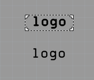
About the 0-width bug in Fritzing 1.0.4 (fixed in later version): After saving the sketch in 1.0.4, and then simply reloading with 1.0.4, the warning about 0 width is also shown, and the logo rendering is broken.
The text suddenly appears bold, which usually happens when the internal rendering exceeds some insane limit (100000 pixel wide text or similar ), and Qt uses a fallback rendering. That insanly large text is then scaled down. Another bug that was fixed in Fritzing 1.0.5 .
Here in 1.0.4, the "zero width"logo and a regular one for comparison, how they look after reloading the sketch in 1.0.4 (or reverting, in the file menu)
When I now try to zoom the logo, it vanishes (in 1.0.4)
About the blank print and the lost sketch.
With the current information, this seems quite high priority.
I am not even sure if it is triggered by zero-size texts form sketches in Fritzing version 1.0.4 and before.
And it seems it comes with potential for data loss.
@vanepp Have you been able to reproduce the blank (white!?) PCB view?
Yes. If you save the zero width fzz in at least 1.0.6, when you load it again pcb view is blank. I think as long as the 0 length text isn’t there pcb should be fine.
1.0.6 won’t create a zero width text item, probably you meant loading a sketch from 1.0.4 in Fritzing 1.0.6, then saving it, then reloading it.
I tried this with all the sketches here in this thread, on Linux, and some on Windows. Both, saving untouched and edited. The sketch always loaded fine in Fritzing 1.0.6 as expected, no blank PCB or similar.
This does leave me with a dilemma since almost all my last work (over 30 pcbs in production) were last edited with 1.0.4.
I guess I should try to open each in 1.0.6 and ‘save as’ to see which ones have corrupted texts? Of course, it’s very likely it happens a bunch since I often copy paste common used elements when building something new.
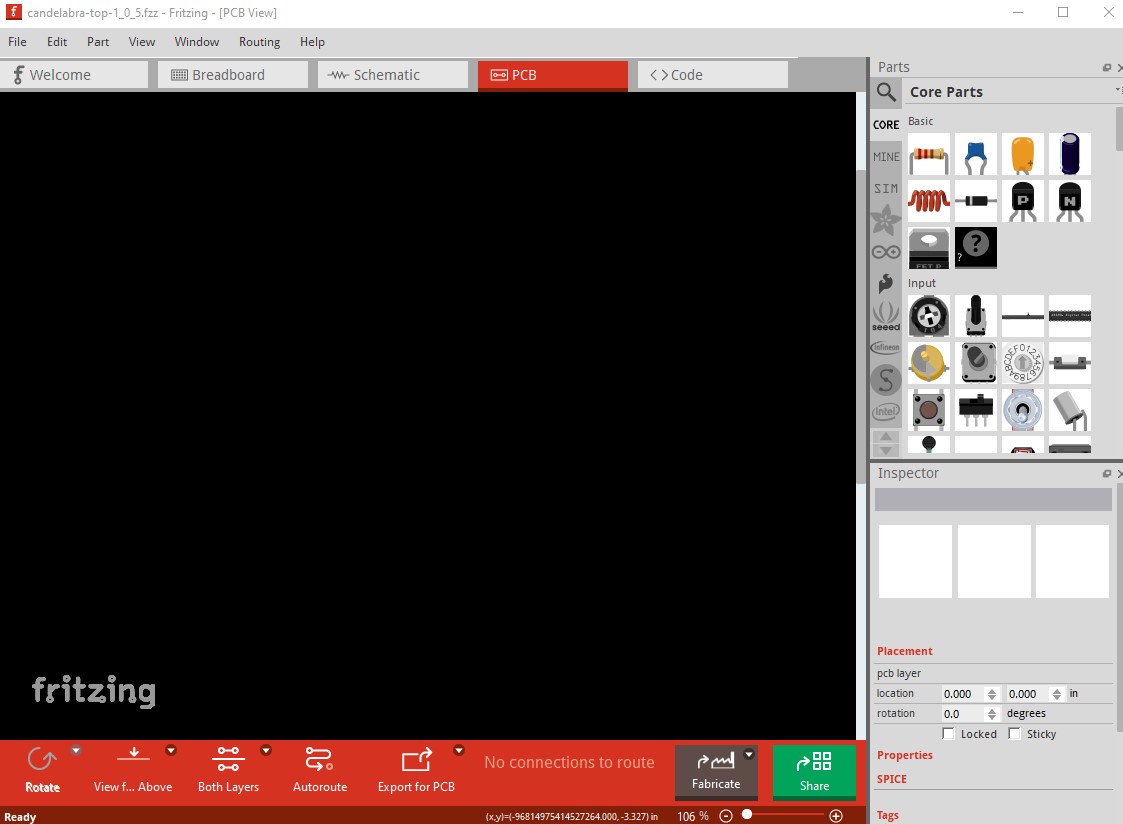
Looks like it may be operator error. I just tried again with the empty-logo-1_0_4.fzz file (which has the 0 width logo) but 1.0.6 displays pcb correctly. It appears this .fzz file which I should have made with 1.0.5
was what I was looking at (as it has no pcb) but when I look at the .fz file there are no zero length viewbox in the logos even though pcb doesn’t show up when loaded with 1.0.6 (although I don’t immediately see a reason why either!)