This is the Motor Circuit I use for Stepper Motors
It’s not really a ‘Part’ but, it can be Copied&Pasted into another circuit…_
Stepper_PH.fzz (24.7 KB)
Stepper_2PB.fzz (24.6 KB)
Stepper_Combo.fzz (27.2 KB)
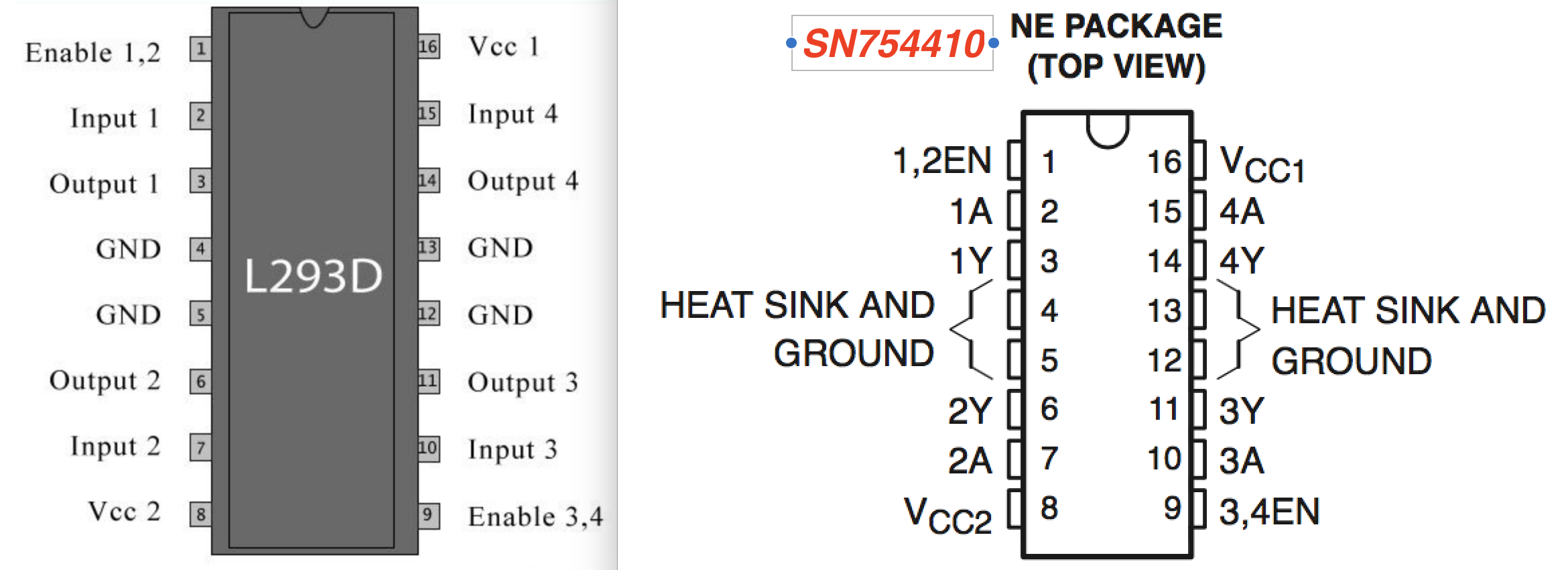
[UPDATE] I have only used SN754410 chips and have not used the L293D chips. But, they appear to have equivalent pins so, I suspect either can be dropped into this circuit (pinout image attached at end)
• Three Circuits but all are the same except for Connector type and locations. Choose the one you want. The Combo version has both connector styles - delete the ones you don’t want (can delete the Traces to them)
• Can be used as Stand-Alone design
• Can copy & paste into other circuits
• SN754410 H-Bridge chip
• One circuit per motor (I use NEMA-17 motors)
• Has added Heat-Sinking copper under the chip (attached to the 4 GND pins - Can delete if not wanted)
• This is Single-Layer design (to facilitate easier HomeMade PCB making. Three jumper wires will be needed)
• Delete corner Mount holes, Silkscreen…etc, as desired
• Example Arduino code included
• Options:
-
LED’s to indicate Running (and Back EMF for hand-turning test)
-
No resistors used but you may choose to add them, depending on your motor supply and LED voltage
-
Thru-holes provided for Capacitor on Motor-Power trace, if desired (I don’t use them)
-
DRC your other circuit first, then paste motor circuit into it (DRC the motor circuit will show Overlapping Errors due to the Silkscreens laying on top of the parts (the way I like them. Of course, you can move or delete them…)
Screenshot and Video Examples
• Pin Header screenshot
• Back EMF (Hand-Turning test on BreadBoard)
• Running Motor
• Adding it to New/Existing circuit