Schematic to breadboard layout

Do you know why he suggested an optical isolated led circuit? It doesn’t seem necessary to me. I don’t know anything about the script stuff (I’m unclear if the referenced article is supposed to be arduino code or midi side code) but I am familiar with led driving. In this case you probably don’t want or need multiplexing, it adds complexity and noise (which is probably why the opto isolator) without much value. Latching shift registers are the best choice for what you want to do. In this case 3 arduino pins control 8 leds, but by adding a second shift register (and some code), 3 pins can control 16 or more leds. It isn’t very fast usually but for human display purposes it is plenty fast enough. There is a tutorial for arduino here (probably one of many and the first I found in a search):

https://www.arduino.cc/en/tutorial/ShiftOut

and this is a basic sketch (schematic only) of the circuit with the connections for a second shift register for 8 (or less) more leds. but without leds (as they connect same as the first one).

3pins_8leds.fzz (12.9 KB)

Peter

I don’t know why he suggested that. Really don’t. Been reading up on it. All I’m trying to do is now add an LED for each track so when the current track is playing it will light up green and when it’s recording it’ll light up red. He said “you need to physically get midi from the midi out of the interface into the arduino. For this you need an isolated circuit which is achieved using an opto isolator.” I need to write this into the program but then I also need to write a script for a pluggin called mobius to assign it to each track switch/foot pedal

Ah that makes more sense. I was thinking he wanted to isolate the led driver, in fact he is trying to isolate the midi device from the Arduino noise wise which probably is a wise idea. I assume this mobius is running on the Mac and sends the midi information to the Arduino via the serial port? Does it need to be bidirectional (I’d assume so as data would seem to need to go both to and from the Arduino to the Mac if the foot switches are supposed to change things on the midi end). Something like this should be what you want (note the optoisolator needs to be high speed and the usual ones are not, the 6N138 mentioned here is high speed enough it appears. ) I’m somewhat surprised these aren’t available on ebay but they don’t seem to be. It would be worthwhile looking for a built one in the midi forums I expect if there isn’t one it is available in 8 pin DIP (easy to use on breadboard, avoid smd ones) for a couple of bucks each. This link shows what you need to do you would need two of these to get both directions:

http://www.midiplayertools.com/Documents/MIDIspecCable.pdf

Peter

Yes mobius is running on the mac in a program called ableton live. Mobius 2 is a plugin that allows looping. Basically I plug my arduino project in through a midi in into my audio interface which then connects into my mac. All the midi commands are sent in through my audio interface into my mac in ableton and mobius. Mobius allows you to use scripts and you can assign a pedal to each command. Okay well I’m new to this, am I using one of these to test the LED’s? Sorry to be a pain but I seem to really struggle to read electronic diagrams

That’s probably a good place to start. You can replace the current 7 or 8 leds with a shift register by plugging it in to the breadboard and moving the led wires from the Arduino to the shift register outputs. Then you need to modify the arduino code to transmit the values that drive the leds to the shift register (the arduino tutorial should help with that). That reduces the number of pins you need on the Arduino from 7 or 8 to 3 for the shift register. Once that is working you can add a second shift register to get even more leds (again you will need to modify the Arduino code to drive them).

Peter

Alright so the use of this circuit is to work out what shift registers I will be using to light up the LED’s I’ll be using. Okay I’ll have to have a go but I think I’m going to need help making it on breadboard as I seem to struggle where to put the components. I just can’t read the diagrams. Sorry to be hardwork, I now understand the need for this circuit and shift registers. Never used them because I’m new to this but all I can do is try. Thank you for your help again, I appreciate it!

It should be fairly easy in that it is similar to what you already have. The LED connections for the resistor and power side are identical to what is there now. The change us that the wire from the bottom of the led that currently goes to the arduino now goes to one of the pins on the shift register. If you drag the resistors and leds in the breadboard of my drawing to the same places they currently are on your working board that is the first step. Then you need to follow the rats nest lines to connect the leds to the correct pin on the shift register chip. Because the rats nest lines are hard to see I often pick one and click on it and move a bit down it. That causes Fritzing to make a wire. The wire is much easier to see and you can click on it an pull it in to a reasonable configuration. If you don’t learn how to do this you probably won’t be able to build this on perf board because the wiring is very similar.

Peter

Okay I’ve had a look at the arduino tutorial you sent me and also found this which will be helpful for me http://www.instructables.com/id/How-To-Make-a-74HC595-Shift-Resistor-Circuit/?ALLSTEPS. I have just bought two 74hc595 shift resistors. Hopefully they should come soon, So for this circuit I need to add my midi adapter onto my circuit don’t I? just I’m struggling to follow this diagram a little. Can I use common cathode led’s with shift registers? Because I need these led’s to light up red and green. So far on my breadboard I have added the midi in adapter. I haven’t added any led’s yet as I don’t know if I can use the led’s that I am wanting to.

just found this https://www.dropbox.com/s/3x17yauwt9g2l7k/ShiftPWM%20Project.pdf?dl=0. This should be really helpful because this is using 16 rgb common cathode led’s where I only need 6

You should be able to make the leds work from one of the programs in the tutorial without the midi adapter being present (the arduino program will drive the leds). Once you get that working you can move on to adding the midi adapter and changing the code to drive the leds. As you have found common cathode leds will work fine.

Peter

Okay well I’m going to give it a go, been really looking into this reading tutorials. I’ve now learnt you need a 74hc595 chip for each colour and also for the common cathode. So you’d need four like on this tutorial. But I don’t need blue so will I still need to wire up the blue? I’ve only ordered two 74hc595 chips will I need more? also will I need 100nf resistors like I keep coming across on the tutorials?http://forum.arduino.cc/index.php?topic=129431.30. Started drawing up a circuit it ain’t finished yet. I know the resistors aren’t correct values, I can’t find any other values in fritzing8 LED shift registor.fzz (12.6 KB)

Um no, not for the cathode anyway. You need a 74hc595 output port (there are 8 on a single 74hc595) for each led of whatever color. There is nothing to stop you from having a red led on pin 1 a green led on pin 2 and a blue led on pin 3. The shift register doesn’t care about colors (you may because of software issues, but the hardware doesn’t) The version with a 74hc595 on the cathode is likely doing multiplexing which you are not. I’d start with the first tutorial I listed which has 8 leds on a single 74hc595 once you get that working then you can add the second 74hc595 to get the second 6 leds connected. As noted you can alternate red and green leds if you like, the hardware won’t care. The software will need to know which output pin has a red and green led to tell which one it should turn on but it too doesn’t care about the color only that it will turn that particular pin on or off. so if you want to end up with 12 leds (6 red, 6 green) you need 12 ports or less than 2 74hc595s Even if the red and green led are in the same package (with 3 wires coming out) the red and the green led each need one port on the 74hc595 (and a resistor between the port and the led). As to the 100nf capacitors they want while they are a good thing to have eventually you probably don’t need them right now. The circuit will work fine without them, their purpose is to reduce noise and this particular application isn’t switching fast enough to make that a big problem.

Peter

I’ve been looking into led’s shift registering with push buttons. Can’t seem to find anything online. But I’ve been suggested to now use Bi-Colour LED which light up red and green when you reverse the power. Do you know much about these? What are my best options to use? Still haven’t recieved my chips so I can shift register.

Recieved my mono jacks today. They don’t fit into my breadboard so I’ll have to add some male headers to the legs. Can I just place them where my push button switches are? Or do I have to connect to lugs together? I remember hearing something about that. Thanks

Okay so I had a play and managed to connect the sockets to my breadboard. I had to move the jumpwire from the top left leg to the top right leg to get it to work. I don’t know if this is correct or not? I had it connected to the top left using push buttons. I need to change the arduino program. Because I checked it through midi monitor and when I press the pedal it says note off then note off. So it needs to be the other way. Think this is because they are actually used as sustain pedals. This is my code for track 1:

if (digitalRead(track1btn) == HIGH && toggle5 == 1){
toggle5 = 0;
if(mode == 0){
midi.write(0x90);
midi.write(0x14);
midi.write((byte)0x00);
delay(300);
}
if(mode == 1){
midi.write(0x90);
midi.write(0x33);
midi.write((byte)0x00);
delay(300);
}

Could I just simply change the (mode == X) so if mode is 0 change that to 1 and if it’s 1 change that to 0?

I think that you want to change the

if (digitalRead(track1btn) == HIGH

to

if (digitalRead(track1btn) == LOW

to invert the sense of the input. With the push buttons, the idle (not pressed state) should have been high and the pressed state is low. With the pedals you referenced (which are nc) the rest state should be LOW and the pressed state will go high. You only need two connections from the sockets as there are really only two inputs and the other two pins are just connected to the others, although I think you have it right if you are getting a change when you press the pedals. It is possible to use shift registers for input (but somewhat more complex) but if you need to do that you may be better off with a keyboard / driver interface board which has both led outputs and switch inputs on a single board (but the software gets more complex).

Peter

Alright, yeah that makes sense my bad. I will try that after. Got ten pedals set out. I haven’t set anything to the tenth pedal yet as I need to write and figure away how to use midi bank to like change a preset or something. I know that these jack sockets the legs are connected to one another at either side. Got them all connected into the breadboard and they all seem to work. Set them just like the push buttons but had to change the jump wire from the top left to the top right for it to work. Checked each one in midi monitor on my mac and everyone says off then on when pedal is pressed. I think this is because they are actually sustain pedals. I don’t really want to use shift register for the pedals. But I definitely need them for the LED’s. Next task is to get these led’s sorted, but I still haven’t recieved my shift register chips which is a little annoying. A guy Suggested I use bi coloured led’s.

There are two kinds of bicolor leds. One has two leads and one has three. You likely want the ones with three leads (which is to say the same as your common cathode leds) as they are a bit easier to drive in that they are the same as your current leds except they are in the same package and share one lead (which goes to the power rail) each of the other leads gets a resistor and connects to a shift register pin. Setting the pin to 0 (assuming common cathode) turns the led on (red or green depending on the pin) and setting it to 1 turns the led off. Setting both pins to 0 will giver you orange as both the red and green will be on.

Peter

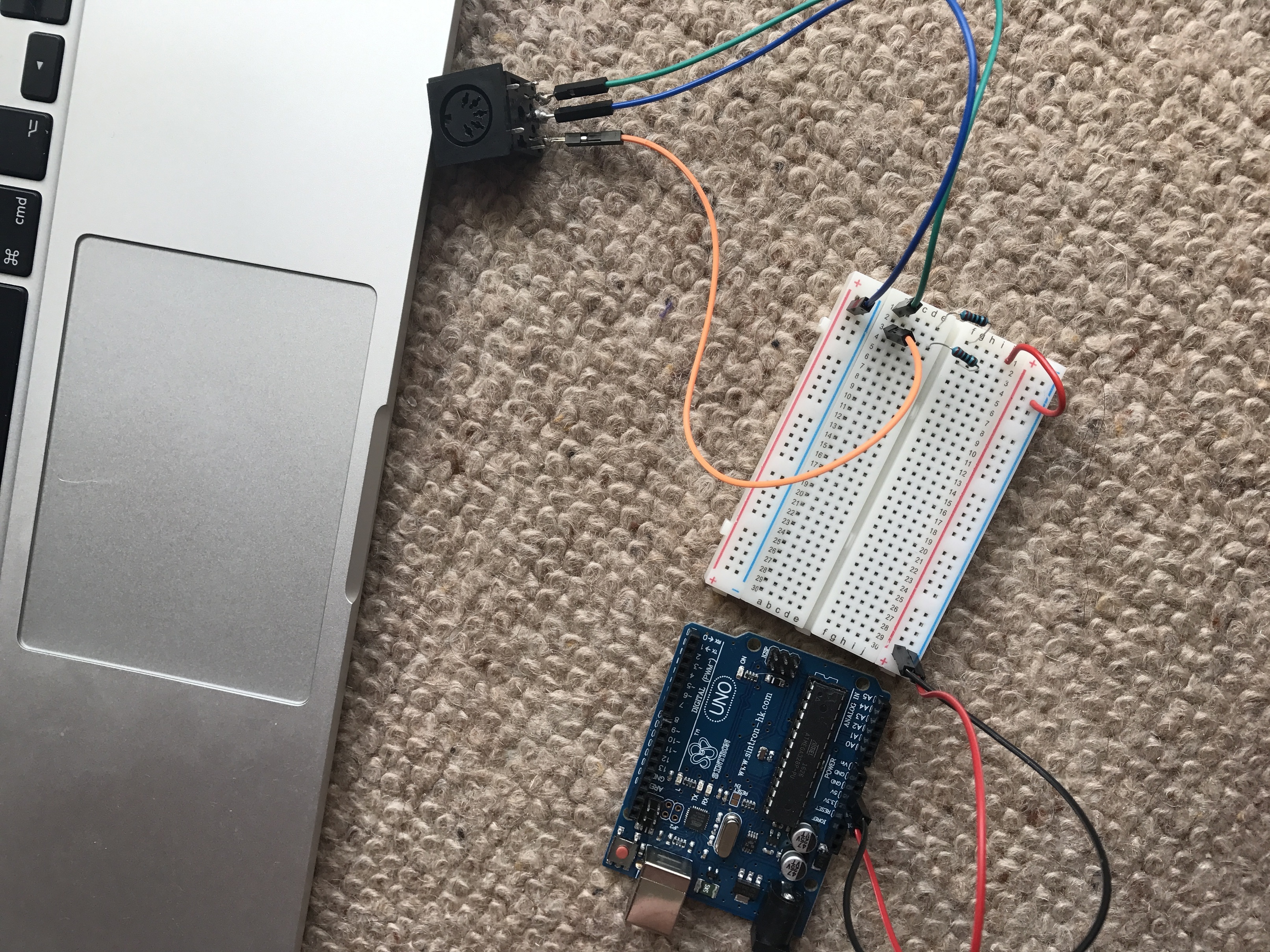
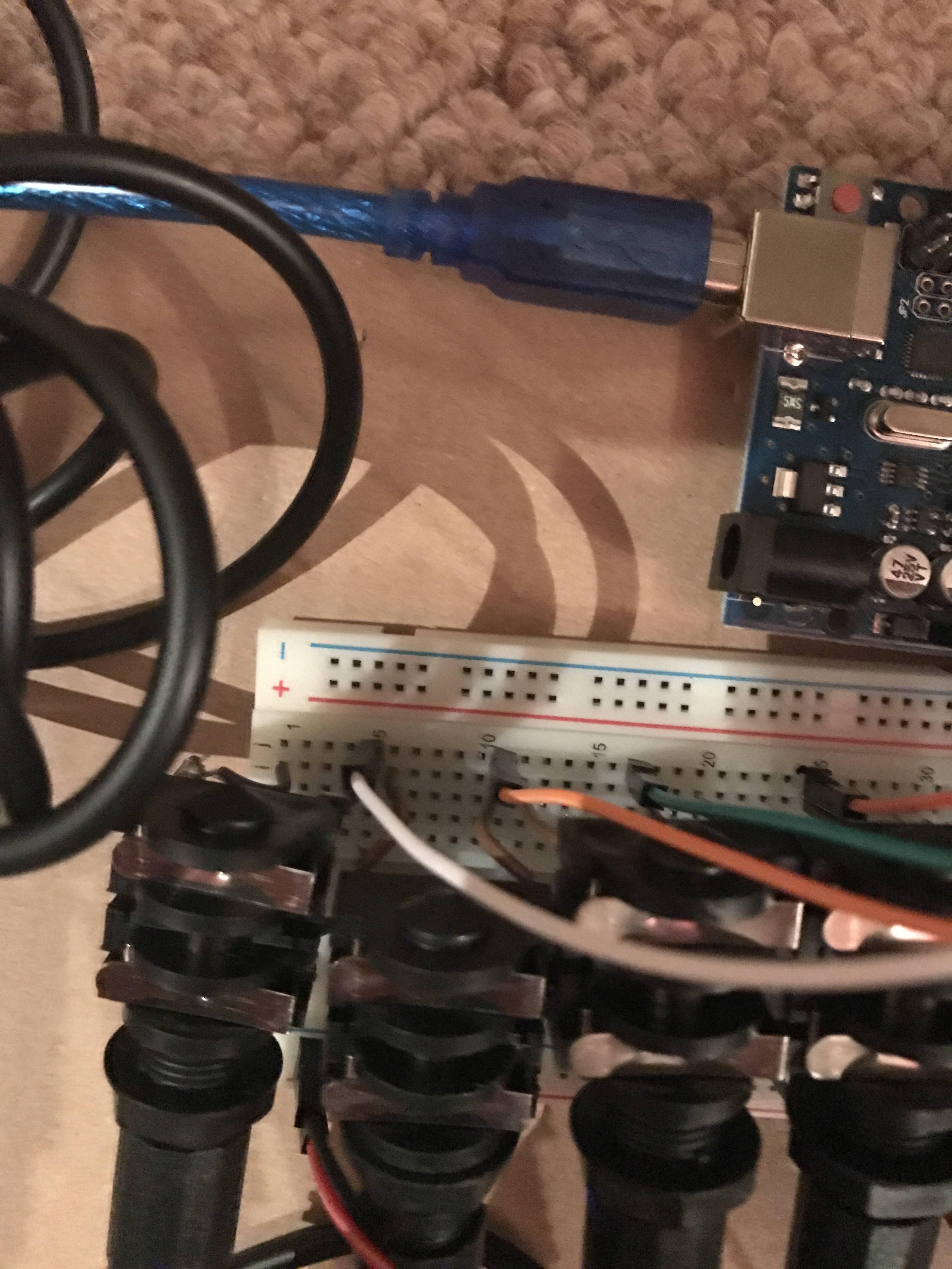
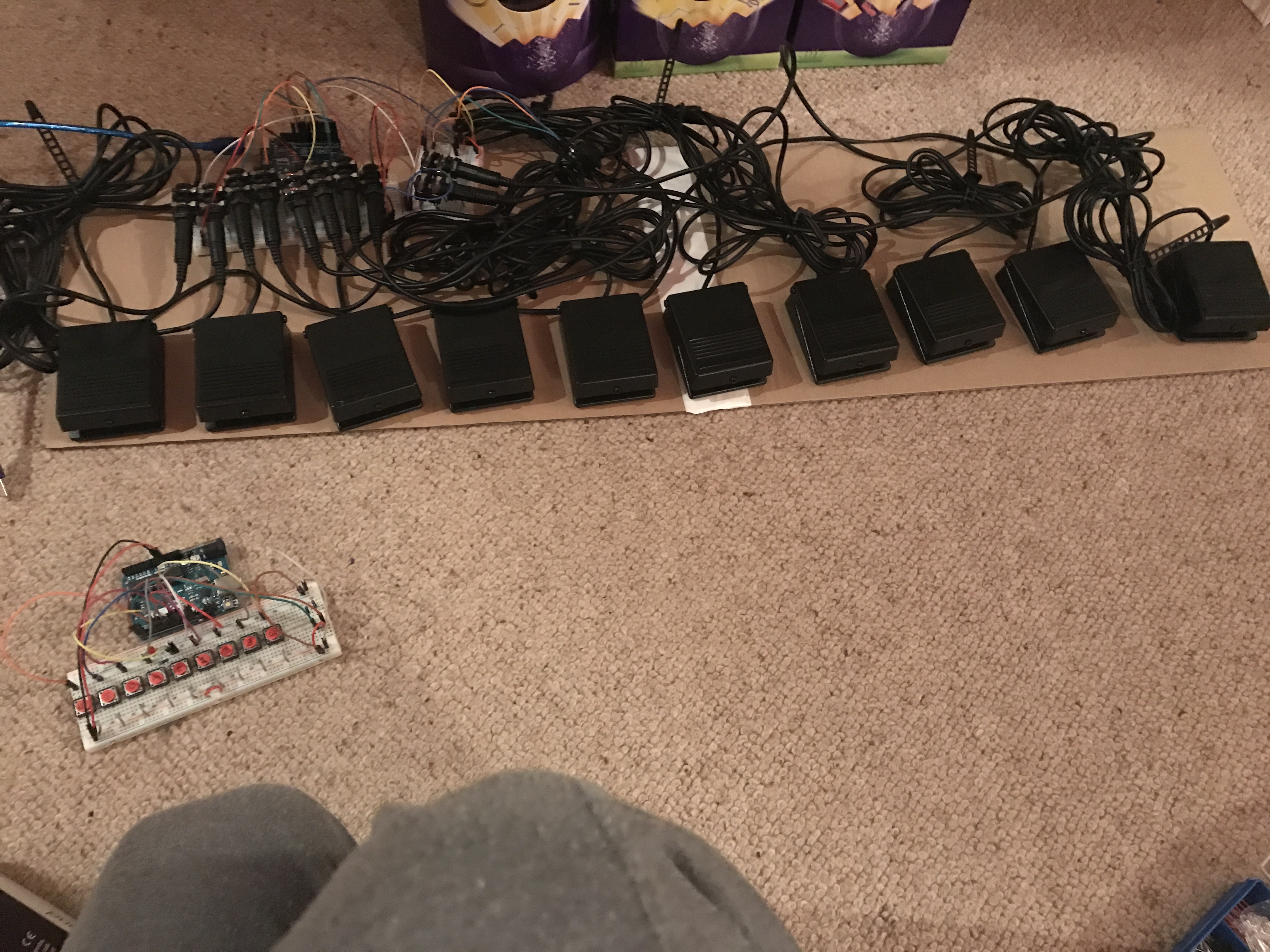
Right well I have got the pedals all working, had to change the HIGH’s to LOW’s and the LOW’s to HIGH’s. All good now, when a pedal is pressed midi monitor says note on and then note off. now its down to the led’s and screens. the led’s I have at the moment are common cathode’s which have four legs, I’m just not sure which led’s to use now, because this guy fredflintstone1024 on youtube built a circuit with shift registers with about 16 rgb led’s I told him what I would like to do and he suggested for me to use Bi-colour led’s. But I just don’t know what route to go down, I hope I get my shift registers tomorrow, ordered them monday and they still haven’t arrived. someone on the arduino forum sent me this info

"In regard to your (common cathode) RGB LEDs, for six of them you need 18 drive lines, so you would be using three 74HC595s. Well, there are ways to reduce that to two; you could just use other port pins for the last two or you could decide not to connect the blue lines.

However, if you want complete versatility including the option to use the blue indicators, then I suggest that rather than fiddling with 74HC595s and resistors, the proper way to do it would be to use a MAX7219. This makes far more sense than worrying about drive current and loading of shift registers not designed for the job. The fact that the MAX7219 is actually intended to drive 64 LEDs is of no concern and the extra expense is minor (click on the illustration).

Given that it involves your own wiring for the LEDs in any case, the sensible way to approach this is to buy a couple (just in case) of the rubbish MAX7219 matrix modules - as a kit - and assemble them without the actual matrix and sockets for same, using the PCB to wire to your own set of RGB LEDs.

This gives you ridiculous available brightness (but totally controllable both as maximum and in steps) requiring no code to continuously multiplex the display; you only update the MAX7219s when you want to change the display which is exactly as you would with the 74HC595s and using the same SPI/ shiftOut process.

It truly is a waste of time and effort doing it any other way, even for 18 LEDs functions only! :smiley-lol: All colour anodes are common, and the cathodes go to six of the eight cathode drivers on the MAX7219 (so in fact, you could use a lot more RGB LEDs - up to 16 in fact!)

So why did I call the modules “rubbish”? Because using these modules with the original matrix displays makes them entirely impractical to stack which is what most people want to do - if you wish to do this you would use the proper design instead. :smiley-lol:

In fact, if you were actually creating a game, you might even consider upgrading to a more sophisticated but relatively inexpensive display using MAX7219 (stackable further) modules:

Plenty of pins left over for four (or more) buttons as described in the forum thread. You may need to do a little more work on the MIDI interface."

The MAX7219 is certainly one solution, something like this would do it as well,

both require software which may not be that simple. I also have something like this that does something like 64 leds and a 103 keys (switches) for a few bucks more that has an adafruit library available for it. There are lots of options, but they get more complex to implement as you go and I think that simple may be better for you for now.

Peter

But that’s multiplexing, I probably will need more led’s for the logo that needs to light green and red also. I’m really struggling as to what to use now. So many options