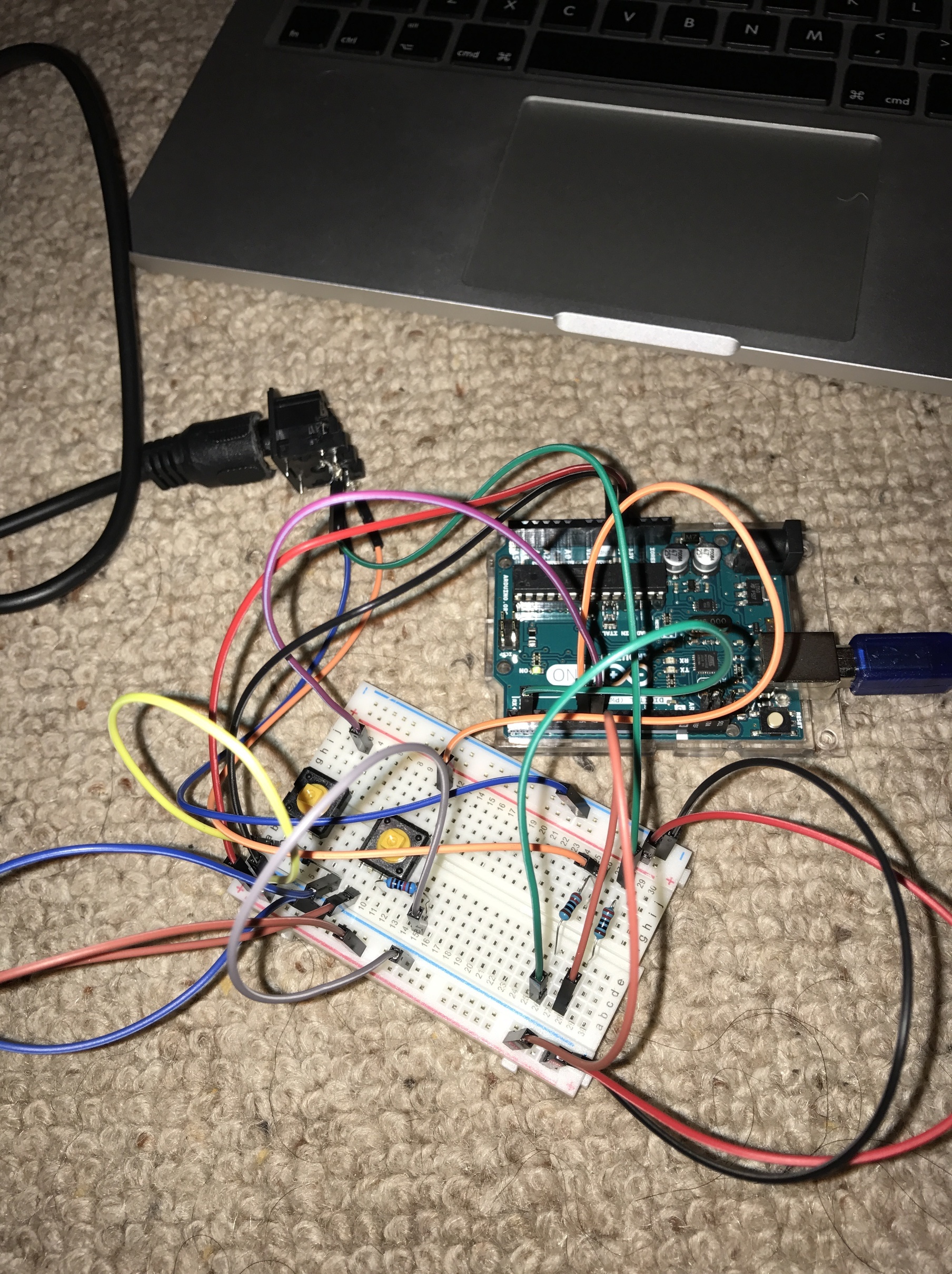
Hello, I’m fairly new to Arduino. I use to make breadboard layouts and circuits a few year back. Only recently I have started to do it again. I’ve done a few different little projects to try and get back into it. But I’m trying to put this schematic of a loop pedal on breadboard and I’m struggling a little got a few of the components on but unsure as to where everything should go. for the pedals I am just using the little pushbuttons. Just wanting to test it out first. I was just wondering if someone could help me out? and show me where each thing should go on something like fritzing or any other software. I seem to struggle a little reading schematic diagrams. All help would be great! thanks. I’m following this tutorial https://www.instructables.com/id/DIY-Chewie-Monsta-Ed-Sheeran-Loop-Pedal/?ALLSTEPS
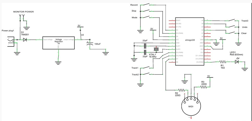
First thing to note is that Fritzing has a bug which tends to corrupt sketches if you make changes in multiple views. So start in one view (since you have a schematic I’d start there) and then follow the rats nest lines to make the connections in breadboard. The first thing I note is that he is using a bare 328 rather than an Arduino, if you are using an Arduino board you don’t need the power supply stuff on the left (the connectors 7805 and diode) as at least the Uno already has them. you also don’t need the crystal or caps by the 328 chip as the Arduino already has those as well. So from the fritzing parts library you need the midi connector, the resistor and led and the push buttons. You need to translate the pins on the 328 chip (hopefully with the standard names) to the Arduino (Uno, mini etc) that you are using (they are again in the parts library)
and drag the parts in to schematic view and connect them all up Identically to the posted schematic (which looks like it was done with Fritzing). Once that is done you will have a jumble of parts in breadboard view with colored lines showing the connections made in schematic. Drag the parts to an appropriate physical position as they would appear in the real world then connect them up following the rats nest (colored) lines in breadboard and you should be done. Connect the physical breadboard up the same way as breadboard view shows and you should be away. If you have problems you can upload the fzz (sketch) file here and the folks here will give you a hand. Note that despite the fact that there is a code window in Fritzing it is a work in progress and can’t at this point actually load the Arduino so you need to use the Arduino IDE to load the software.
Peter
he is using a bare 328, he soldered a pcb up. But I’m using an Arduino Uno. I have a diagram of the 328 and uno so I should be able to to translate the pins. Eventually when I come to build this I will need the things on the left. Because its a midi loop pedal with a screen in it. I will have a go now to redraw it as a schematic and see what it does. I will upload it along with the Arduino program
Layout.fzz (10.0 KB)
I have started to redraw the schematic, but I haven’t drawn it onto the uno. But I still don’t think I’ve done it correct and also I’m not sure as to where everything should go. Too many lines going on
It looks fairly close to right but you look to have hit the bug caused by modifications in more than one view from the dotted rats nest lines connecting unused pins on the 328. I’d advise starting fresh with the Uno R3 from parts as that’s what you will use. I’d suggest putting 1K or so pull up resistors to +5V on the Arduino pin side of the switches as well so they switch the port between 0 (when the switch is closed) and 5V when its open. Otherwise you look to be pretty much fine. Then follow the rats nest lines in breadboard to get the wiring for the breadboard side.
Peter
Layout UNO.fzz (8.4 KB)
I have drawn this up on the uno, don’t know if I have missed anything out. the parts are all over the place on the breadboard view. Didn’t want to go moving them and hit the bug again. also I’m not sure where the correct places they would be on a breadboard. I have used just normal switches, instead on the push buttons that I am using but again I’m not sure how they line up and positions of them. Sorry for being hard work. I’m slowly learning bits
Not a problem, while we like to say Fritzing is intuitive, in truth that’s only compared to other EDA programs it is still complex. I’ve used EDA programs for 30+ years and am still learning Fritzting. I’ve found one source of data base corruption: your schematic has 2 R1’s one on the midi connector and one on the led. I didn’t know you could do that but I always let Frtizing pick the part numbering. Correcting that by deleting the LED R1 and dragging in a replacement didn’t correct things (indicating data base corruption) so I started from scratch. On the way by I added the 5 pull up resistors for your switches that you need. That gets us this (with nothing done in breadboard):
Layout UNO_updated_schematic.fzz (16.9 KB)
Then I switched to breadboard to arrange the layout. You will see in the jumble of parts that you seem to only have 2 switches and not enough resistors. That’s because Fritzing loads them all on top of each other and you have to drag them away (while avoiding creating wires which I find almost impossible, and so have to often highlight the wire I didn’t mean to create and right click and delete it). That gets us to this one that has bb placed but not routed:
Layout UNO_updated_bb_placed.fzz (18.0 KB)
Then I went through and actually connected the rats nest wires (using the top and bottom power busses for power and ground which gives us the complete
layout:
Layout UNO_updated_complete.fzz (27.8 KB)
You can change it around to whatever makes the most sense to you, this is just one way (not necessarily the best way ![]() ). The PB switches for instance could be connected with wires to somewhere not on the breadboard if the switches you actually use won’t fit easily on the breadboard. Hope this helps!
). The PB switches for instance could be connected with wires to somewhere not on the breadboard if the switches you actually use won’t fit easily on the breadboard. Hope this helps!
Peter
Thank you so much this has helped massively! I am using these push buttons, the only thing is they have 4 pins instead of 2 like the bread board has. I’m only using these to test first

This is the arduino code that I am wanting to run, obviously with the things on the left hand side of the original schematic I uploaded like the screen.
[#include <SoftwareSerial.h>
SoftwareSerial midi(8,7); ///RX TX
int clearbtn = 14;
int recordbtn = 2;
int stopbtn = 3;
int track1btn = 5;
int track2btn = 6;
int track3btn = 11;
int modebtn = 4;
int undobtn = 13;
int led = 9;
int toggle1 = 0;
int toggle2 = 0;
int toggle3 = 0;
int toggle4 = 0;
int toggle5 = 0;
int toggle6 = 0;
int toggle7 = 0;
int toggle8 = 0;
int mode = 0;
void setup(){
pinMode (clearbtn, INPUT_PULLUP);
pinMode (undobtn, INPUT_PULLUP);
pinMode (recordbtn, INPUT_PULLUP);
pinMode (stopbtn, INPUT_PULLUP);
pinMode (track1btn, INPUT_PULLUP);
pinMode (track2btn, INPUT_PULLUP);
pinMode (track3btn, INPUT_PULLUP);
pinMode (modebtn, INPUT_PULLUP);
pinMode (undobtn, INPUT_PULLUP);
pinMode (led, OUTPUT);
digitalWrite(led, HIGH);
delay(250);
digitalWrite(led, LOW);
delay(250);
digitalWrite(led, HIGH);
delay(250);
digitalWrite(led, LOW);
delay(250);
digitalWrite(led, HIGH);
delay(250);
digitalWrite(led, LOW);
delay(250);
midi.begin(31250);
}
void loop(){
if (digitalRead(undobtn) == LOW && toggle1 == 0){
toggle1 = 1;
if(mode == 0){
midi.write(0x90);
midi.write(0x41);
midi.write(0x01);
// delay(300);
}
if(mode == 1){
  midi.write(0x90);
  midi.write(0x36);
  midi.write(0x01);
  // delay(300);
}
}
if (digitalRead(undobtn) == HIGH && toggle1 == 1){
toggle1=0;
if(mode == 0){
midi.write(0x90);
midi.write(0x41);
midi.write((byte)0x00);
delay(300);
}
if(mode == 1){
  midi.write(0x90);
  midi.write(0x36);
  midi.write((byte)0x00);
  delay(300);
}
}
if(digitalRead(clearbtn) == LOW && toggle2 == 0){
toggle2 = 1;
if(mode == 0){
midi.write(0x90);
midi.write(0x01);
midi.write(0x45);
//delay(300);
}
if(mode == 1){
midi.write(0x90);
midi.write(0x37);
midi.write(0x45);
//delay(300);
}
}
if(digitalRead(clearbtn) == HIGH && toggle2 == 1){
toggle2 = 0;
if(mode == 0){
  midi.write(0x90);
  midi.write(0x01);
  midi.write((byte)0x00);
  delay(300);
}
if(mode == 1){
  midi.write(0x90);
  midi.write(0x37);
  midi.write((byte)0x00);
  delay(300);
}
}
if(digitalRead(recordbtn) == LOW && toggle3 == 0){
toggle3 = 1;
if(mode == 0){
midi.write(0x90);
midi.write(0x10);
midi.write(0x45);
//delay(300);
}
if(mode == 1){
midi.write(0x90);
midi.write(0x35);
midi.write(0x45);
// delay(300);
}
}
if(digitalRead(recordbtn) == HIGH && toggle3 == 1){
toggle3 = 0;
if(mode == 0){
midi.write(0x90);
midi.write(0x10);
midi.write((byte)0x00);
delay(300);
}
if(mode == 1){
midi.write(0x90);
midi.write(0x35);
midi.write((byte)0x00);
delay(300);
}
}
if(digitalRead(stopbtn) == LOW && toggle4 == 0){
toggle4 = 1;
///Serial.println(“mute/stop”);
if(mode == 0){
midi.write(0x90);
midi.write(0x07);
midi.write(0x45);
//delay(300);
}
if(mode == 1){
midi.write(0x90);
midi.write(0x34);
midi.write(0x45);
//delay(300);
}
}
if(digitalRead(stopbtn) == HIGH && toggle4 == 1){
toggle4 = 0;
if(mode == 0){
midi.write(0x90);
midi.write(0x07);
midi.write((byte)0x00);
delay(300);
}
if(mode == 1){
midi.write(0x90);
midi.write(0x34);
midi.write((byte)0x00);
delay(300);
}
}
if (digitalRead(track1btn) == LOW && toggle5 == 0){
toggle5 = 1;
if(mode == 0){
midi.write(0x90);
midi.write(0x14);
midi.write(0x01);
// delay(300);
}
if(mode == 1){
midi.write(0x90);
midi.write(0x33);
midi.write(0x01);
// delay(300);
}
}
if (digitalRead(track1btn) == HIGH && toggle5 == 1){
toggle5 = 0;
if(mode == 0){
midi.write(0x90);
midi.write(0x14);
midi.write((byte)0x00);
delay(300);
}
if(mode == 1){
midi.write(0x90);
midi.write(0x33);
midi.write((byte)0x00);
delay(300);
}
}
if (digitalRead(track2btn) == LOW && toggle6 == 0){
toggle6 = 1;
if(mode == 0){
midi.write(0x90);
midi.write(0x15);
midi.write(0x01);
// delay(300);
}
if(mode == 1){
midi.write(0x90);
midi.write(0x32);
midi.write(0x01);
// delay(300);
}
}
if (digitalRead(track2btn) == HIGH && toggle6 == 1){
toggle6 = 0;
if(mode == 0){
midi.write(0x90);
midi.write(0x15);
midi.write((byte)0x00);
delay(300);
}
if(mode == 1){
midi.write(0x90);
midi.write(0x32);
midi.write((byte)0x00);
delay(300);
}
}
if (digitalRead(track3btn) == LOW && toggle7 == 0){
toggle7 = 1;
if(mode == 0){
midi.write(0x90);
midi.write(0x16);
midi.write(0x01);
// delay(300);
}
if(mode == 1){
midi.write(0x90);
midi.write(0x31);
midi.write(0x01);
// delay(300);
}
}
if (digitalRead(track3btn) == HIGH && toggle7 == 1){
toggle7 = 0;
if(mode == 0){
midi.write(0x90);
midi.write(0x16);
midi.write((byte)0x00);
delay(300);
}
if(mode == 1){
midi.write(0x90);
midi.write(0x31);
midi.write((byte)0x00);
delay(300);
}
}
if (digitalRead(modebtn) == LOW && toggle8 == 0){
toggle8 = 1;
if(mode == 0){
  midi.write(0x90);
  midi.write(0x17);
  midi.write(0x01);
  // delay(300);
}

if(mode == 1){


  midi.write(0x90);
  midi.write(0x30);
  midi.write(0x01);
  //  delay(300);
}
}
if (digitalRead(modebtn) == HIGH && toggle8 == 1){
toggle8 = 0;
if(mode == 0){
mode = 1;
midi.write(0x90);
midi.write(0x17);
midi.write((byte)0x00);
digitalWrite(led, HIGH);
delay(300);
}
else if(mode == 1){
mode = 0;
midi.write(0x90);
midi.write(0x30);
midi.write((byte)0x00);
digitalWrite(led, LOW);
delay(300);
}
}
}
The buttons aren’t a problem, they are in parts as well in the first part of core in fact. The 2 pins connect together and are electrically the same as the one you used in the sketch. I see that you don’t really need the 5 pullup resistors as well, he sets the internal pullups in the code although they won’t hurt anything either.
Try it and see what happens 
Peter
I have had a go at adding the actual buttons I am using, but I don’t think I have done it correct. And because I have edited it in breadboard view it has messed up with the bug in the schematic viewLayout UNO_updated_complete edit.fzz (27.0 KB)
You have several problems in your updated version: first on the breadboard the top and bottom 2 horizontal lines are all connected together horizontally (to distribute power and ground usually). The rows above them to the center line for 5 holes connect together vertically the 5 after the center line also connect together vertically (but are separate from the bottom 5) so you have (in a single vertical row) power ground 5 connections bussed together another 5 connections bussed together and power and ground again. The next row horizintal repeats this pattern. The new switches have 2 terminal on each end connected together so as wired on your breadboard the switch isn’t doing anything both because it has both terminals connected to a bussed row and because the actual switch is between the two terminals on the left (connected together both internally in the switch and by the breadboard buss) and the two terminals on the right are connected together but don’t connect to anything else. If you moved the resistor right 2 positions so that it and the wire connecting it were on the other side of the switch that would work, but you can’t physically connect it like that, the switch takes too many positions on the breadboard. To fix this I went back to my original Layout UNO_updated_bb_placed.fzz file which has the complete schematic but nothing on the breadboard (safest place to start), then deleted the current switches in schematic then dragged in and placed the 5 new switches, relabeled and reconnected them. Switched to breadboard and routed one of the switches to show one way they can be connected successfully (they will also work if you leave the switches where they are in your version, connect the resistor between the top 5V bus and move it right two holes then connect a wire from the E column to the F column on the breadboard (across the middle gap) so ground comes in on the left of the switch and the other contact of the switch connects (via the jumper from E to F) to the resistor and the wire to the Uno and the top of the resistor connects to 5V. Then when the switch is closed it will short the bottom of the resistor and the UNO pin to ground as desired. It is possible that if you start from your (or my) original circuit and connect the switches in breadboard correctly it may work, the corruption doesn’t always happen (it may be caused by wiring errors like the ones here even if corrected later), but the best way as noted is to start from the schematic only view (or a breadboard only view) as I did for this version:
Layout UNO_updated_bb_placed_new_switches.fzz (20.6 KB)
Peter
Thanks for the updated version, I had a go at moving the switches and tried to follow your instructions and I struggled. I got a few in place then it all went bad, I ended up giving up. I have a question I need 6 LED’s on this project. I have added 5 more, please would you have a look at it? I wasn’t sure if I was alright to just add them downwards from the original LED. I need to yet program these but need the correct positions firstLayout UNO_updated_bb_placed_new_switches edit.fzz (24.8 KB)
I forgot to mention I’m thinking of adding a adafruit LED ring too. Not sure if I’ll be able to, but I do need something similar for on the left of the loop pedal it lights up 3 different colours and spins around. And possibly might need to add a adafruit led panel for the logo.
Yes how you did it is correct, the one signal and power and ground wire that I added in breadboard look to be what caused the corruption (making this sketch a good test case when I finally get around to poking at the fritzing source ![]() ) and you only had 5 leds not 6 so I went back to the copy that had only the schematic done (like this new one) and made the changes there. You should keep a copy of this one to add your new leds later with nothing connected (yet) in breadboard. I added a 6th led (you can delete it if you really only want 5) and positioned the switches and removed the pull up resistors as unneeded as the software is setting the internal pullups correctly and that is 8 less things to wire which is always worthwhile
) and you only had 5 leds not 6 so I went back to the copy that had only the schematic done (like this new one) and made the changes there. You should keep a copy of this one to add your new leds later with nothing connected (yet) in breadboard. I added a 6th led (you can delete it if you really only want 5) and positioned the switches and removed the pull up resistors as unneeded as the software is setting the internal pullups correctly and that is 8 less things to wire which is always worthwhile ![]() .
.
If you have a url I’ll have look at the interface requirements for both of these (search isn’t working for me on Adafruit’s site and I couldn’t identify either in a quick look). You may run out of I/O pins is your most likely issue but there are ways around that with expander boards.
Layout UNO_updated_bb_placed_new_switches_new_leds.fzz (23.4 KB)
Peter
I still need to add the things that were on the left of the original drawing like the screen, power plug and monitor power. But I need to add two screens somehow.
I’m thinking of using something like this for the Chewie II logo unless there is a better way?: https://www.proto-pic.co.uk/adafruit-neopixel-neomatrix-8x8-64-rgb-led-pixel-matrix.html
and then use one of these for the knob on the left that lights up in circular motions: https://www.proto-pic.co.uk/neopixel-ring-12-x-ws2812-5050-rgb-led-with-integrated-drivers.html
The neopixel will be bright, but is also timing sensitive (although adafruit has a library for it) and power hungry (with bad peak currents sometimes). Depending how much brightness you want/need a tft color display might do but it won’t have anywhere near the brightness of the neopixels. For the power section I’d chose to use a 5V (at however many amps the neopixel wants) regulated wall wart in stead of the 7805 regulator / wall wart combination as the 7805 is only good for 1 amp max and I think the neopixels may want more than that. From the adafuit data sheet (worst case) 60 ma per led the 64 led one is ~ 4 A (3.8) and the other is going to be 720 milliamps so you may need around a 5A wall wart to power the leds. I’d suggest another 1 amp or so wall wart to power the processor to keep the supply noise from the neopixels (which will have large current spikes) away from the processor. Note they recommend a large (1000 UF 6.3V or higher) capacitor on the pixel supply as well. You will need to be careful with your grounds and wire sizes at this current level, I doubt that you will be actually drawing 4 amps in this application and a 2A wall wart may do fine, but I’d measure the current draw with your image displayed to be sure and more current available won’t hurt, it just costs more.
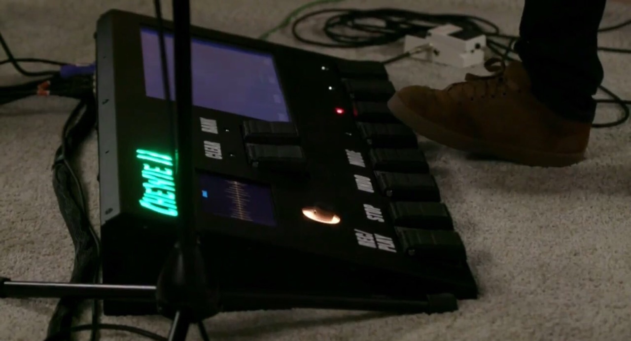
(edit: I just realized you appear to be trying to display the words
Chewie II
as the logo. An 88 (64 led) panel will only display the C of that (as characters are typically 57 dots) to display that word (assuming that is what you want) you would need a tft panel in the 480*320 or larger range (and they get expensive fast as the size increases).
Peter
There is only 1 wire on the breadboard layout. Tried to read the lines on it but there are so many. Built a circuit this morning from http://www.makeuseof.com/tag/make-midi-controller-arduino/. Had some trouble with the midi monitor on my mac. Also think it was down to the leads. I have a cheap midi to USB cable. And it eventually sent a message to the monitor using it. But my normal midi cable don’t think it’s connecting right to my audio interface. Because of the shielding On the outside. So I think I’ll have to cut come off.
Yep there are a lot of wires, but if you want to do this you are going to have to get used to that. Unfortunatly the one wire that is there is wrong, it is connecting a signal line to ground and needs to be deleted, the ground is in fact on the other switch lead (I rearranged the switches at one point). While there really isn’t an easy way to make the breadboard connections, the one I find most useful is to start on one pin (for instance the left most switch after you delete the black wire that is there now) and highlight it and move along it a bit. That will create the wire to its first connection point (in a straight line) now (and this is the tricky part) avoiding clicking on any of the other rats nest lines (or more usually, using the delete wire dialog to remove new wires to get them out of the way) route that one wire in a reasonable way to its associated other end. Then pick another one and do the same until they are all done. The created wires are easier to see than the rats nest lines and the created wire will route to where it should go.
This looks like a good place to start, it is simpler than your original circuit and should let you get the rest of your connection chain solid before trying your original circuit. You will want to correct the connection problem before trying much more. The last thing you want when making a new circuit is to not know whether your new circuit isn’t right or you have a cable / connection problem. You need to have a solid connection to your midi device so the only unknown in the path is your new circuit. I don’t know much about midi but it looks like this is just an RS232 serial connection to your Mac. The most likely problem here is a speed mismatch between the Arduino and the USB midi converter. There are a set of standard speeds that serial cables run at and if you have a mismatch then the connection either won’t work at all or gets errors which makes it work sometimes. As noted you want to get this corrected first so this section of the path is solid.
Peter
I have managed to sort out the error. It now works through my audio interface and is sending midi messages to my mac. I have moved everything closer in on my breadboard. So I could possibly and more buttons or even LED’s. think I need to get the longer breadboard and more buttons. Only have 3 buttons at the moment. Happy it is now working after hours of messing around!