I did find this tutorial online, not sure if it’s helpful but I think it says a little bit about what each wire is inside the jack lead? https://www.google.co.uk/amp/www.instructables.com/id/DIY-Powered-Pedal-Board-with-Input-Jacks/step5/Soldering-and-wiring/%3Famp_page%3Dtrue
I have read a review about the pedal on amazon saying be careful the polarity can match sometimes also on this website https://www.sweetwater.com/store/detail/DP2Pedal it says that it’s normally closed
Electrically these will work fine, but now you need to put on your mechanical engineer hat (these projects need many hats ![]() ) and consider how you are going to mount and use the jacks. I expect this is going to be used in performances and can expect to have the cords tripped over and in general mechanically pulled on. Solder joints are weak mechanically and don’t like (i.e. tend to fail which you don’t want) when stressed mechanically. So I’d suggest your best bet is chassis mount jacks where the holding nut that bolts it to the panel is not part of the electrical connection (I think I showed some a while back in this thread) and connect flexible wires from the connection tabs to the Arduino which won’t be mechanically stressed. As to the pedals they are pretty simple in that they are just like your push button switches the two wires are electrically (if not mechanically) identical to your switchs. As you point out these pedals are normally closed rather than normally open (as your current switches are). The only difference that makes is that you would need to change the Arduino code to consider a 0 as the switch rest state (with you current NO swirches 1 is the rest or not pushed state).
) and consider how you are going to mount and use the jacks. I expect this is going to be used in performances and can expect to have the cords tripped over and in general mechanically pulled on. Solder joints are weak mechanically and don’t like (i.e. tend to fail which you don’t want) when stressed mechanically. So I’d suggest your best bet is chassis mount jacks where the holding nut that bolts it to the panel is not part of the electrical connection (I think I showed some a while back in this thread) and connect flexible wires from the connection tabs to the Arduino which won’t be mechanically stressed. As to the pedals they are pretty simple in that they are just like your push button switches the two wires are electrically (if not mechanically) identical to your switchs. As you point out these pedals are normally closed rather than normally open (as your current switches are). The only difference that makes is that you would need to change the Arduino code to consider a 0 as the switch rest state (with you current NO swirches 1 is the rest or not pushed state).
Okay so all these will work then? I’m actually planning to keep the wiring inside. All these electrics I want to encase in a housing so tripping over the wire and putting stress on the cable shouldn’t be a problem. If these parts will work I just really need some help as to how and where they connect in my circuit
Yep the connectors shown should work. They connect exactly like your current switches there are two sets of pins connected together (giving you two connections) one goes to ground and the other to the terminal of the Arduino just like the switches on the breadboard. If you solder wires to one of them you can connect it in place of a switch on the breadboard to test it. As noted you will need to change the software to change the programs sense of when the switch is active to make them work the same.
Peter
Okay only thing I don’t know is the actual size of the jack plug it just doesn’t say anywhere. I’m guessing it’s standard, when you say change the software do you mean about the pedals polarity being the opposite? Them connectors have four pins does that matter? Because it’s like the current switches I have in breadboard which have four legs
I’m still confused how to wire these jack sockets but I found a tutorial explaining it here http://www.ampmaker.com/se-5a-chassis-wiring-part-1-962-0.html
The size of the jacks you referenced was somewhere in the 6mm range which I think is probably the metric equivalent of 1/4" so the size may be correct, only trying them will tell for sure. Yes the software needs to change because the pedal you are going to use is the opposite (normally closed when your pushbuttons are likely normally open) of your current push buttons. Again as with the switches 2 pins or 4 pins doesn’t matter you only have to get the connections correct. Again as with the push buttons there will be a connection between two of the pins, from the picture of the jack you showed I think it likely that the two pins to the rear of the jack connect together (and thus one wire wants to go there) and the two front pins connect together and the other wire goes there. From the picture again it looked like the metal contact runs across the body of the connector to the other pin, if so one wire wants to connect to either of those pins and the second wire wants to connect to either of the other pins. What you don’t want is to connect both wires to pins that connect to each other. That won’t break anything, but it also won’t work (as the connection will always be made even if the switch is pressed). I don’t think the tutorial you referenced is a good bet. Having looked at it it appears to me to be shorting the pins in the manner I just described and if it is confusing me, I don’t think its a good plan for you ![]() . Come to think of it an easy test for this is to use one of your leds. Replace the ground wire on one of the leds (where the other lead of the led goes through the resistor to 5V) with the two wires from the socket. With nothing plugged in to the socket the led shouldn’t light (because the circuit is open) plugging in the pedal should cause the led to light. With the pedal plugged in, operating the pedal should make the light go out.
. Come to think of it an easy test for this is to use one of your leds. Replace the ground wire on one of the leds (where the other lead of the led goes through the resistor to 5V) with the two wires from the socket. With nothing plugged in to the socket the led shouldn’t light (because the circuit is open) plugging in the pedal should cause the led to light. With the pedal plugged in, operating the pedal should make the light go out.
Peter
They are the correct size, just annoyed that I’ve ordered them from China when I can get them the same price from the uk which would be quicker. Couldn’t find them in the uk till today. I understand what you mean now about the software needing to be changed. Each pedal might be different, I have ordered all my pedals. Struggled with ordering them they must be pretty populous as I could get the quantity I needed so I ordered from different companies. I’ll have to try and work out the connections when I get them or try and look them up online. But I’m finding it hard to find anything

Didn’t know they made 4 pole ¼" audio plugs. I know they make 1/8"(3mm) ones.
https://ae01.alicdn.com/kf/HTB1dpBVPXXXXXXhXXXXq6xXFXXXW/High-QualityWhite-3-5mm-4-pole-3-ring-Gold-Plate-Audio-font-b-Video-b-font.jpg
The little SCH at the bottom right tells you what it does.
I know but I don’t understand it
It’s like any 4 pole connector, it’s just that it has a segmented rod interface. Each section connects with the fingers in the socket.
Sorry I’m really new to all this so it’s going straight over my head. If I was to put it on my breadboard o could simply replace the current switches that have four pins? Which pin is which? I found a website that explains about them well http://info.mammothelectronics.com/blog/audio-jack
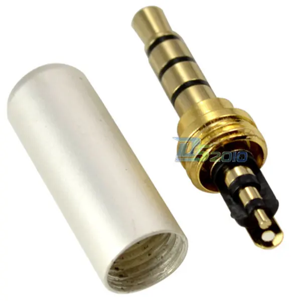
Part of the problem is the referenced 4 pole plug isn’t what he has  . He actually has 1/4" mono plugs (and thus 2 wires out, not 4.) For the plugs you actually ordered from the picture of them they look like the one on the left in the photo above but without the middle pin at the back. From the photo above the two front pins are connected together (and thus that is where one of your wires connects).The two outside pins at the back would then also connect together (just like your current push button switches and the other wire connects to one or the other of those.
Peter
I’m baffled with these mono jack sockets now
They are pretty easy: while like the switches they have 4 pins, there are really only 2 connections 2 pairs of the pins (like the switches) are connected together so all you need to do is figure out which 2 pins connect together and connect one wire to that and one wire to the other two pins that connect together to give you the two wires from the pedal to replace the switch on the breadboard with. If you get it wrong the pedal won’t do anything (because the connection is always closed) but it also shouldn’t damage anything. Moving one of the wires to another pin should both fix it and make it work.
Peter
Okay I now understand that. I just now need to know which pin is which. Since these are ready for pcbs could I connect these to my current breadboard? Could I simply replace the current push buttons I have at the moment? Also I’m lost with the pcb arduino. I know you can make them onto pcb. But I don’t know how to use pcb. Think I once used one years back at high school. Also I don’t know which arduino I need as I still want to add at least 6 rgb common cathode LED’s, some sort of light for the logo and some sort of light like the pixel ring for the knob on the left. But I’ll run out of pins using my arduino uno
Yep if you solder a piece of 22 gauge or 24 gauge solid wire (such as extra lead cut off from a resistor if you don’t have a suitable piece of wire) to the socket pin it will fit in to the breadboard to test with.
Peter
Okay so forget the jack sockets for now I will mess with them when they arrive. I’ve been talking to the guy who made the original pedal in the tutorial on instructables. I’m wanting to add multiple led’s to the circuit. I’ve still to find a way on how to program them and creat scripts on mobius the vst. Found this here which should help me. http://www.circularlabs.com/forums/showthread.php?t=1420. But I’ve been suggested to build a isolated circuit which is achieved using an opto isolator. And instead of buying a bigger arduino to look into charlieplexing, multiplexing and shift registers which is a good method to control more LED’s than pins I have. I don’t know which is the best method I know they have there advantages and disadvantages. But do you know much about this?