Actually the holes are fine. They are 0.040 same as the 1n40001 diode. Large pads are a good bet for potentially high current applications. In Inkscape hole size can be calculated as hole = diameter_of_pad - (2 * stroke-width). At the suggested scale (as this file is) that works out in thousands of an inch. In different scales you need to multilpy the scale factor in (I usally convert to the standard scale as being easier on me  ). Good parts, several of you are getting good at making parts which benefits all of us. A couple of minor nits though:
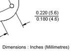
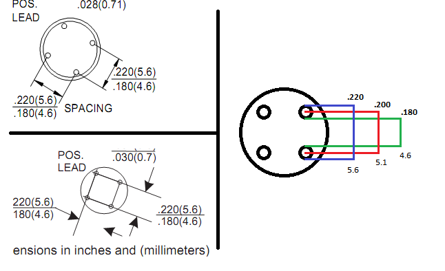
bridge rectifier round
Error 80: File
‘part.bridge_rectifier_round_200mil_eef1f87a78563dd0550e80252d00af13_1.fzp.bak’
At line 53
Both terminalId and legId present, only one or the other is allowed.
this doesn’t appear to be bothering Fritzing (although Fritzing crashed when I deleted this part after moving one of the bendable legs to make sure it worked so maybe it is in some way.) You are getting very good if you can make bendable legs work, I usually still have trouble because there are undocumented rules (different parts of the legs must be specific graphic constructs and the legId portion must be outside the viewbox).
Error 18: File
‘part.bridge_rectifier_round_200mil_eef1f87a78563dd0550e80252d00af13_1.fzp.bak’
Connector connector0terminal is in the fzp file but not the svg file. (typo?)
svg svg.breadboard.bridge_rectifier_round_200mil_d4b37b7d708ee9291c0aa1b4b3048108_3_breadboard.svg.bak
Again Fritzing ignores the missing terminalId (which typically isn’t in breadboard anyway) and uses the center of the svgId instead. This is typically a problem in schematic as the terminal will be in the wrong place.
Warning 25: File
‘svg.pcb.bridge_rectifier_round_200mil_d4b37b7d708ee9291c0aa1b4b3048108_3_pcb.svg.bak’
At line 17
Silkscreen layer should be above the copper layers for easier selection
in pcb view
This is a warning because it doesn’t hinder function. It is however desirable the have silkscreen as the first group in pcb because it will select the silkscreen before it will select copper if slikscreen is last which usually isn’t what you want.
bridge rectifier TO-269AA
much the same complaints with only this new one:
Error 47: File
‘part.bridge_rectifier_TO-269AA_36b7c4180bd36c649f4cab927fa6d6c5_9.fzp.bak’
At line 87
LayerId copper0 doesn’t match any in View pcbView layerIds [‘silkscreen’, ‘copper1’]
which indicates you have copper0 definitions somewhere in the fzp file but it isn’t in the layerId definitions (which means the later instances will be ignored). As I said overall a good job.
Peter

 ). Good parts, several of you are getting good at making parts which benefits all of us. A couple of minor nits though: