Hello,
i’m currently working on a Fuse Box for SK6812 LED Strips, since all of the 15m Strips would at full brightness end up using 38,4A i’m going to seperaten them into 2m pieces each which and end up with 4.8A per Trace and Wire.
My Idea behind the Box is that i’m going to use a Wemos D1 mini which monitors the Voltage and current of the 8 LED Strip Lines and shuts down the line as soon as it hits 4.8A with a Relay the Fuses behind it, are just a Fallback and Fast Blow 5A Fuses.
Also i tryed to at least do all of the traces that are Ground to the Bottom of the PCB to do a mass fill later.
I think most of the traces should’nt be a Problem but i’m still running into 2 issues.
I don’t know how i’m going to measure the 5A since the limit of the INA219 is 3,2A i did a sketch using a ATiny and a ACS712T but that one is limited to current measure and i don’t know if i can just put one of the ATiny Pins on the Phase or not.
I’m still confused because originally i wanted to use SSR Relays to shut down the Lines but now i have read somewhere that it’s not so easy if you are using DC Current like i do. And Heat will be a big Problem… So i’m a bit lost there now.
Everything else should be straight forward the 74hct245 is a logic level shifter to stabilize the DIN on the Strips.
PCF8574 is a bus expander to control the relays and the TCA9548A is a i2c expander which was orginally for the INAs.
I also asked the some questions on the fastLED and Teensy forum but… Someone i want get any help there.
The current capability of the INA219 is set by the size of the shunt resistor. Changing the value of the shunt resistor changes the maximum current detectable. That said I would use a INA3221 which has an internal A/D and gives a digital output such as this:
There is a hack (involving cutting traces) on the net to make the inputs take 3 different voltages but you likely don’t need it. You may need to reduce the value of the shunt resistor (currently .1 ohm) to get 5A full scale, you would have to check the data sheet to see what full scale is at present. As to your relays I’d use power MOSFETs such as this:
If you don’t want the module, you can use a logic level power MOSFET instead (and optoisolate it if you choose). You do need to make sure you drive the MOSFET fully on (thus the logic level gate drive) to avoid burning it out.
The thing is that the Resistor on the INA is an SMD Part which would be quite hard to replace without the nessecarry tools (that i don’t have) this was also the reason why i preferred THT and DIP over SMD and SOP Parts on my Board, because it would be easier to solder and replace. Even if the whole PCB get’s a big bigger than.
And yes i also thought about the Mosfet with a logic gate but was still confused with the explanation of how to choose the right one for it, because of the VDD, VGS and other Values that they have. So if i did a mistake there all of the current would end up in Heat. But of course a direct solution would be better than a another pcb on the board. I also don’t get why there are 2 mosfet on the board should’nt one be enough?
You need to find a logic level MOSFET (i.e. VGS for full on is ~2.5V not 8 or 10V like a non logic level MOSFET) and fairly high current so RDSON is low (and it thus doesn’t heat up much due to internal resistance). There are lots around.
I think this one could work it has a VGS from 2-4 and supports up to 9A i just don’t understand the Diagram in the datasheet… At which point do i have which temperature? Oo
Nope, you want an IRL (logic level) type and probably 100A as in the board I referenced. If you look at the gate-source voltage against current chart in the data sheet, it isn’t fully on until about 8V gate-source and you don’t have that much drive voltage. The 100A rating typically doesn’t cost that much more and reduces RDSON (to reduce IR drop at 100A) which helps you even at 5A as a lower RDSON reduces the power due to IR loss in the MOSFET. That is more important for your application than switching losses as you aren’t switching. I have to go out for a bit but I’ll have a look at what I’d suggest a bit later.
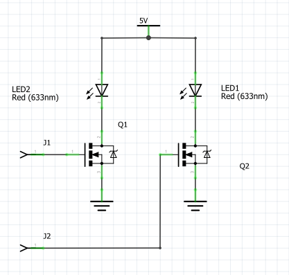
Good one problem solves which leads directly into the next one… Because i still does’nt understand why i need more than 1 Mosfet for a single circuit line. At least i have seen many boards and shematics that use one mosfet for gnd and one for the phase which irritates me quite a bit, since i thought it would work just like a relay or switch. So that the circuit shares a common ground but the phase is divided through the mosfet and controlled by the gate.
I don’t see any reason for more than one MOSFET per circuit. You are right it acts like a switch. Do you have a web site that uses two just in case I’m missing something?
Not directly… Most of the stuff was for the RGB Channel of non microcontrolled LED Strip anway… But for example the Module that you posted used one for the ground and one for the cathode. If i understond the shematics of it right
I only just got those modules and haven’t yet played with them but they are two independent channels as far as I know. One of those modules would control two of your led strips, one on each fet although the ground needs to be common. That is correct, the grounds are connected together internally so you would need to switch on ground, but this should work fine.
Where the leds are actually your led strips. The grounds being interrupted, the logic in the LEDs will not see a voltage on the signal lead when they are off and thus shouldn’t care.
Yeah, thats also something i’m currently researching so the source of the mostfet should always be ground same a the drain to the led strip right? Which would mean that the cathode is directly connected to the strip… Is’nt that a saftey issue? Lets say for example that the strips comes loose and falls onto the floor, the next person that touched it on one of the Pads is new grounded to earth and becomes a shock…
Assuming the leds are powered by 5V or 12V (not 120V) that it technically true, but the voltage is low enough it isn’t an issue. Your fuses protect against a short in that situation, they will blow from the over current (The fuse needs to be in the high side not the ground side though in case the strip has found a ground somewhere else.
Before i scrap the whole design now to change it to one using mosfets… Would’nt it be also an option to use normal Coil Relays for it? Most of them are for 30V DC anyway.
I still have one of the wemos d1 mini relay shields laying around here which is also rated for 10A and 24VDC i will just test it as soon as my new breadboard arives. Oh, and don’t get me wrong, i’m greatful for your help… It’s just that i have a bad feeling about it, knowing that there still is a current on a wire.
Anyway i still need to somehow measure the voltage and the current
I’d have a look at the TI sensor I listed, in your case it will measure 3 channels with each board. The shunt resistors are surface mount, but they are reasonably large so it shouldn’t be too difficult to replace them with something smaller, like about a 0.016 ohm resistor to keep the sense voltage around 80mv and about a 1 W resistor should do. In practice you may just be able to use a piece of wire, but buying a resistor may be easier. I don’t know of any of the current sensors that come in dip packages any more (although there may be some)