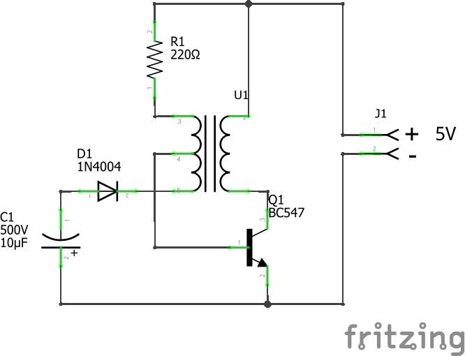
I made this circuit based on a vid from The Signal Path because it’s simple. The circuit has to be simple, cheap, with easy to find parts.
When I apply 5V - voltage doesn’t makes much difference - it only puts out 55V across C1, when I need 300V.
The only transformers I could find were in old transistor radios, so is the transformer wrong?
I did some Googling and it said the only way to work out unknown transformers is test and measure.
Could it possibly be that your text equipment is just too much of a load? Nixie tubes only run at 2 - 5ma.
It could also be that you need the neon indicator tube as part of the oscillating circuit. Their properties can actually be used to create a logic circuit due to the difference in the ignition and maintaining current requirements. http://www.dos4ever.com/ring/ring.html
Yes your likely problem is the transformer turns ratio. I’d guess this is an 8 ohm output transformer with an about 80 ohm secondary from the voltage you are seeing. For 5V in and 50v out you have about a 10/1 turn ratio (which translates approximately to the impedance ratio of 8 ohms to 80 ohms). The transformer you need wants a 80/1 or so ratio to increase 5V to 400V. I think the value of the capacitor (and possibly the impedance of the transformer) will control the oscillation frequency of this (it is quite a clever simple oscillator circuit I must admit!). Note that you need 1kv of isolation which tends to be expensive (a 100V isolation is in the $2/$3 range for 600ohm/8ohm, 1KV isolation is $14 or more). What might work best is a 220volt to 6V power transformer. If you feed the 6V side with 12V the line side should produce 440V. I’m not sure this oscillator circuit will work (it would need to be in the 50/60hz range to work correctly) but a 555 oscillator at 60hz driving a MOSFET in place of the transistor should work. Note you want to be careful around the 400V output, with the cap that is getting to be enough energy to kill you if you touch it.
edit: One of these may do as well, somewhat pricey and shipping may be an issue
So that’s how you work out transformers. This is 1-ish ohm to 14-ish ohms - my DMM doesn’t seam that accurate - but my cheap Ebay transistor checker shows 3.2mH to 32.8mH which is close to 10:1.
It’s hard to find small transformers on the cheap sites, and even harder to get specs - my local only gives mH of the windings -, and expensive is kind-of a deal breaker because the whole timing-light is $27AUD.
I’ve got a 240V to 5V USB I can try, but like you said it needs an osc because it’s only 2 wire on the secondary.
Actually you can’t really use the resistance to determine the windings. Both windings are most likely wound with different wires (thicker for low voltage side, the thinnest possible on secondary). This means the resistance for 1 wrap of one side will be different from the resistance of 1 wrap on the other side. The only way you can actually tell is to input a known full wave AC voltage and measure the output.
As @sublimeartistry pointed out resistance is a poor indicator of turns ratio because of wire size, but inductance of each winding should be at least in the ball park for turns ratio and from there measuring with the desired signal at the frequency that you want to use is the real world test that works.
This one is a possibility, it looks to be about a 62/1 turns ratio which means you would get 375V out with 6V in from an oscillator drive circuit (I’m not sure what the circuit you have will do, it appears to be different than just the turns ratio, as it says it uses self inductance which I don’t know how to calculate). Primary winding insulation may also be an issue as I expect it is probably 100V as most of the transistor ones seem to be and 400V may cause arc over in the primary as the insulation fails. As you note finding transformers is getting more and more difficult, I guess they aren’t popular because of cost and the various switching regulators now available, but it is a pain when you need one.
You are likely to find that this doesn’t generate enough current to charge the capacitors in any reasonable time which may be an issue in this application. For a camera a 30 second recharge time isn’t an issue because you typically don’t take photos that fast, for a strobe I expect (but don’t know for sure) you need a quicker recharge cycle to be ready to flash at each trigger. If you can’t, you may get timing variation depending on how many triggers occur between recharges (which since the two are unrelated will vary with time). Given that as far as I can see this project is aimed at possibly non electronics people, hand built strobe lights present a danger. As noted earlier a charged 400V cap can present a life threatening danger if you aren’t used to dealing with them (such as shorting them out with a clip lead before working near them to avoid shocks) which may be a liability issue. If you can get enough brightness to be usable, I think the LED solution is more likely to be more cost effective with much less danger.
Peter
Even at 55V it makes a pretty big zap, so 300V is a lot. I might not release this one to the Speeduino forum if I get it working because parts aren’t easy to find, but I still have to make a compact one that I’m going to mount on the car and try to film the ignition advance curve as I drive around because I want to get an idea of what the factory ECU ignition curve looks like.
EDIT - I just realise it might not work because the energy released from the flash interferes with cameras.
I just realised I need an rpm display in the vid, ouch!
Looks like the 240V to 5V wall wart trans isn’t any good.
It’s ferrite core and has 3 separate windings :-
1 - 0.3 ohm 0.05mH
2 - 1 ohm 0.6mH
3 - 9.4 ohm 4.7mH
I’ve got lots transformers out of a ATX PS , but now I’m thinking anything with a ferrite core isn’t going to work.
I don’t see the average Joe building this using simple Ebay/Ali or from their local elec shop, because parts are a real PITA to get. Unless you want to pay high prices at the big wholesalers - it’s cheaper buying the timing light - , no high voltage caps - 100V max -, only 1 horseshoe Xenon, and 1 maybe 2 transformers. I think the death of analogue is killing this.
Looks like LED is going to be the only option, so I’ll have to sort that out properly.
When I was young and built hot rods the only timing light we had was one that ran the Xenon bulb directly off of the coil voltage and went inline with the plug wire (no induction coil).
I tried to find some info for you but the internet has very little info about these old things. I did manage to find a single picture of one.
I do believe they cause a little reduction in the spark on #1 but it is minor and should easily be accounted for. One of these should be easy to make. Connect the bulb between your distributor and your plug and you are done.
Actually an in-line timing light was my first too, and yes it’s not as bright as my next cheapest clamped TL. It might actually be a neon bulb with a big reflector because mine was orange-ish like a neon.
I reversed my el-cheapo, but it’s too expensive to build compared to an Ebay one.
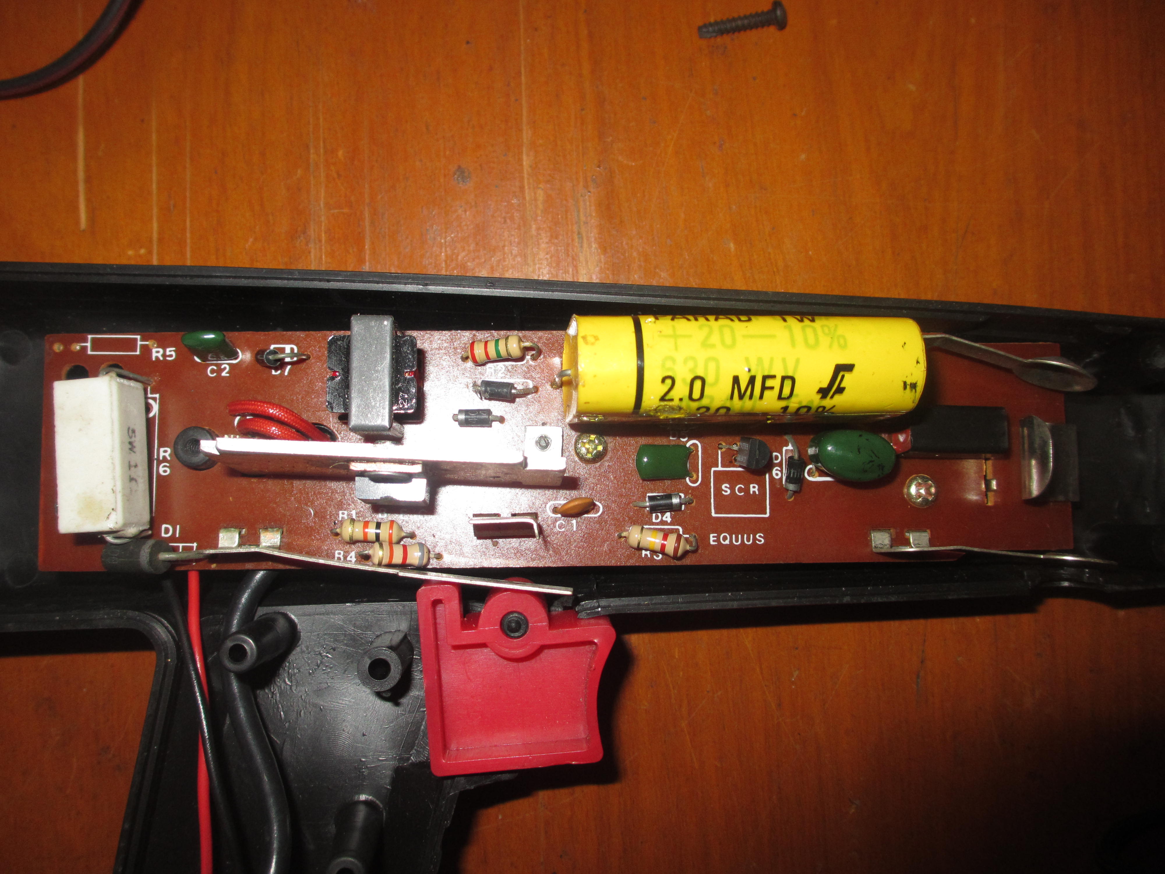
From what I read EQUUS is the cheapest.
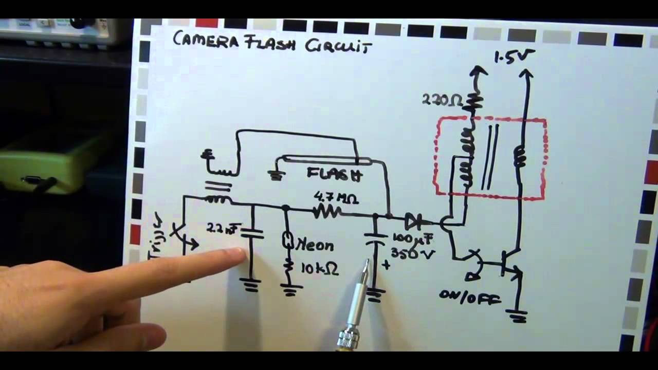
I may have a source of cheap circuits you could use for powering a timing light. Electroluminescent wire inverters. They run around 100vac so would require a rectifier.
or
or
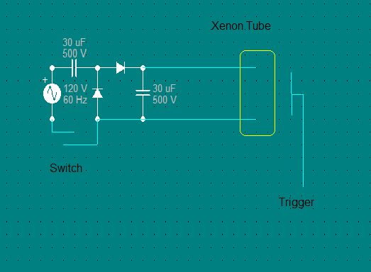
Also with your original circuit you could make a voltage doubler with a few diodes and caps to hopefully get up to your xenon ignition voltage.
In this instructable about a diy mains powered timing light he uses a voltage doubler followed by the circuit you last posted. It looks like you wouldn’t even have to rectify the output from an EL wire inverter to make it.
I haven’t ever worked with xenon tubes so I decided to do a little research on them and came across this page http://donklipstein.com/xeguide.html it has a lot of information on working with xenon flash tubes. What I learnt during my read was to achieve quick bright flashes like are required on a timing light you may need anything from 200v to 1.6kv depending on your tube size and flash duration. Also you would likely want the smallest length/diameter tube you can get your hands on to reduce the required voltage.
I was looking at those mains voltage doubler TLs, but it just seams too dangerous and not portable.
Things are getting dangerous now because my 400V PS arrived.
My cheap 9 LED torch with a direction reflector also got here, so just waiting for the COB before I test Peter’s LED TL. I’m interested if the 555 adds lag to the trigger, and I need a lot of light to direct it at the engines accurate timing marks because you can’t get close enough for a weak light.
I remember reading a timing light test in a car mag years ago - maybe a decade - and pretty much all had lag. From memory the cheaper the more lag, but even the expensive SnapOn had 1º lag.
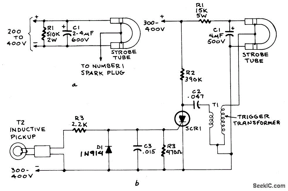
My guess would be yes it does. I think this is why they use Xenon bulbs as the metal around the bulb is used to trigger the existing charge to emit light and is done without any circuity adding hysteresis. The charge from the plug wire pushes the voltage in the tube above its ignition voltage and viola a burst of light. At least in the simpler schematic. In the fancier one you have a 1-4kv trigger transformer and added circuitry that would likely add some lag.
I wonder what kind of amperage you get at that voltage.
The CCFL for $4 looks promising if you can turn it down internally without a transformer.
The other LED circuit didn’t seam to have lag when compared to my Xenon light - the leading mark looked correct if you ignore the artifacts -, so it would be interesting what this one does on the actual graduated engine marker.