Hi! Fritzing newbie here with a question about an existing component, the Camdenboss CTB0158-x family of pluggable screw terminals. First, this specific component seems to be no longer available, and the similar parts I found on Amazon have significantly different dimensions (i.e. silkscreen outline doesn’t match part). This alone wouldn’t be a showstopper, but the hole size is much too small. The holes appear to be sized for a normal header pin, not the much larger (~1.3mm) pins of this type of connector. Drilling out the holes would have removed the through-hole plating, so I had to file the pins down to fit (not something I want to do very often).
I haven’t yet attempted to climb the learning curve of modifying the part or creating a new one, so I thought I’d check with the Forum first to see if there’s an easier solution.
Note that the Properties description of the part includes “Hole size 2.7mm”. Obviously that’s not right…
On the bright side, I was able to install Fritzing, design the attached PCB, and have it fabricated in less than 2 weeks. How cool is that?
Thanks for any help! Nilo Shield v1.fzz (42.0 KB)
This one should be fairly easy (or as easy as any part modification anyway ). If you have a data sheet for the part you want and the number of positions I can modify one of the Camdenboss parts for you. You can also try a google search of the form “fritzing part part-number” (where part number is the part you want). Someone else may have already made one.
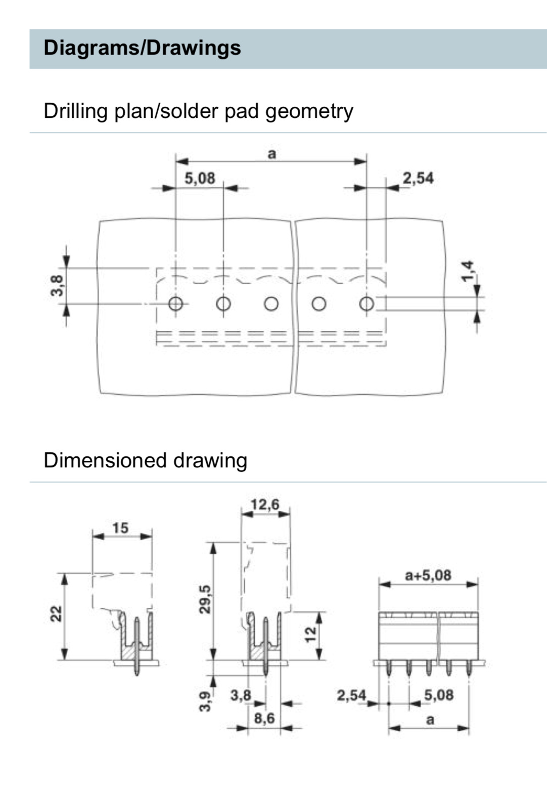
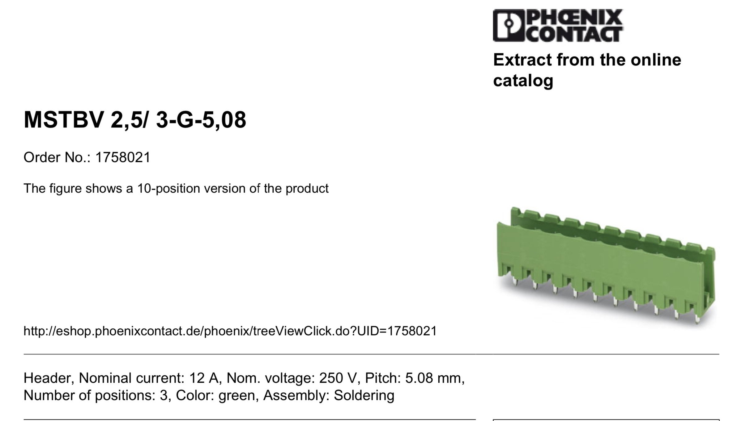
@vanepp, thanks very much for your offer! I wasn’t able to find a data sheet for the connectors I purchased on Amazon, but the dimensions in the attached data sheet are very close.The forum won’t let me upload a PDF, so I took a couple of screenshots of the most relevant portions of the datasheet.
This is the male PCB-mounted portion of the terminal block. I need 2-, 3- and 4-pin versions of this.
Thanks again!
These three should do the job. I was lazy and didn’t change the layout on breadboard, but the silk on pcb should be the correct size for the new connectors and the holes are 0.055in
Awesome! No worries about the breadboard view, since I don’t use that anyway. However…sorry to be picky, but can you change the silkscreen width (dimension perpendicular to row of pins) to 8.6mm as shown in the data sheet for the male, PCB-mounted portion of the connector? The 15mm dimension you used is for the (right-angle) female portion when its plugged into the male header. In my application, this portion will overhang other components or may be off the edge of the board.
Thanks so much!
Hello Peter,
I ordered a PCB with the original CTB0158 90 degree from fritzing.
The core Part are with 0.8 mm and according to the sheet they have 1mm.
The Reality says also 1mm
But ups right now I see my real part 90 degree is a CTB9359 so forget the sentence before!
How can I modify the PCB holes of the CTB0158 90 to get there 1.1 pinholes?
Cool thing will be choosable hole diameter for the pins in the library part.
Let me say an universal CTBx part
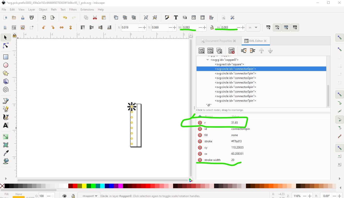
That is somewhat easy (assuming you use Inkscape and are familiar with part creation.) You need to obtain the svg file (exporting the core part and unzipping the .fzpz file is the easiest way to do that.) Then modify the holes like this:
in the image above the scale is set so drawing units are 1/1000 of an inch, so the stroke-width of 20 is 20thou. The original pad diameter was 0.08in, giving a 1.016mm hole (less some for the plating through, although I think the board houses compensate for that.) To change that I set the pad height and width to 0.0833in (1.1mm) to give a 0.0433in hole (1.1mm.) However doing that moves the starting position of the pad, so I then recorded the radius of the new hole (31.65) then undid the changes to the pad diameter and instead changed the radius of each pad in xml editor to 31.65. This enlarges the circle around the center which leaves the pad correctly positioned. I also made a variety of changes to all the svgs to meet the graphics standards (not required, but desirable!) That results in this corrected part which has 1.1mm holes:
but should otherwise be identical to the core part. To verify this export the part as gerbers and edit the drill.txt file. Here I missed (by accident not intention!) one pad
; NON-PLATED HOLES START AT T1
; THROUGH (PLATED) HOLES START AT T100
M48
INCH
T100C0.040000
T101C0.043300
T102C0.038000
%
T100
X017410Y004084
which gives the original hole (0.040in) the new holes (0.0433in) and the holes for 0.1in headers (0.038in) which are used to verify the connectivity of the new part. The correct file looks like this:
; NON-PLATED HOLES START AT T1
; THROUGH (PLATED) HOLES START AT T100
M48
INCH
T100C0.038000
T101C0.043300
%
T100
X029460Y011235
with only the 0.0433in holes and the 0.038 holes. That should do what you need.
 Thank you again!!