I create a PCB and build a part for more pinheaders. More info
Wing-Stack-Extension for Arduino Uno.fzpz (457.1 KB)
I create a PCB and build a part for more pinheaders. More info
Wing-Stack-Extension for Arduino Uno.fzpz (457.1 KB)
That is not a valid (complete) part file. All of the svg files it contains have the same graphics, matching what should be only the breadboard (and maybe icon) view. None of the svg files contain the layer information required by Fritzing. The rows of gnd and +5V pins should all be included in the “gnd” and “+5v” bus entries in the fzp file.
It is valid to create a breadboard view only part, but that is not the way to do it.
Why not? No one should use any other view in fritzing - they are stupid - IMHO
You can use my part or not - I just offer it
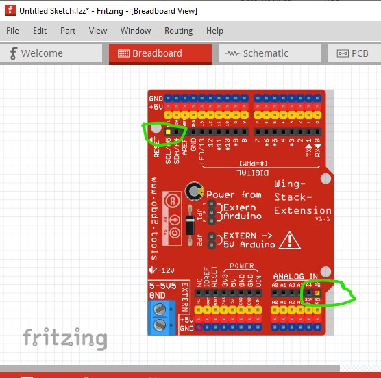
While you are free to post any part you like, as @microMerlin pointed out this one is substandard. It lacks a breadboard layerId which means that it will not export as an image (the part will be blank when you export the sketch as an svg, jpg etc. ) The buses are not correct. Using A5/SCL as an example the A5 pin on the Arduino is correctly bused to the arduino SCL/A5 pin on the top (note that when I click on the A5 pin on the bottom the SCL/A5 pin on the top also lights yellow as it should.
However neither of the extension pins which should also be lighting yellow (because they are also bused) are doing so because the bus is incorrect.
All of the GND and +5V pins should be in a bus (as they all connect together) and they are not. The pins in the fzp file should be defined as male not female so that connectors show up in breadboard as red when not connected and turn green for connected. It would be trivial to copy in the Arduino schematic and add the few extra pins you have added, but not required. It would be better to modify the fzp file to reuse the breadboard svg (which at some 4megabytes in size is huge and thus a waste as well!) to reduce the size of the part. Your part may work as is, but as noted has problems.
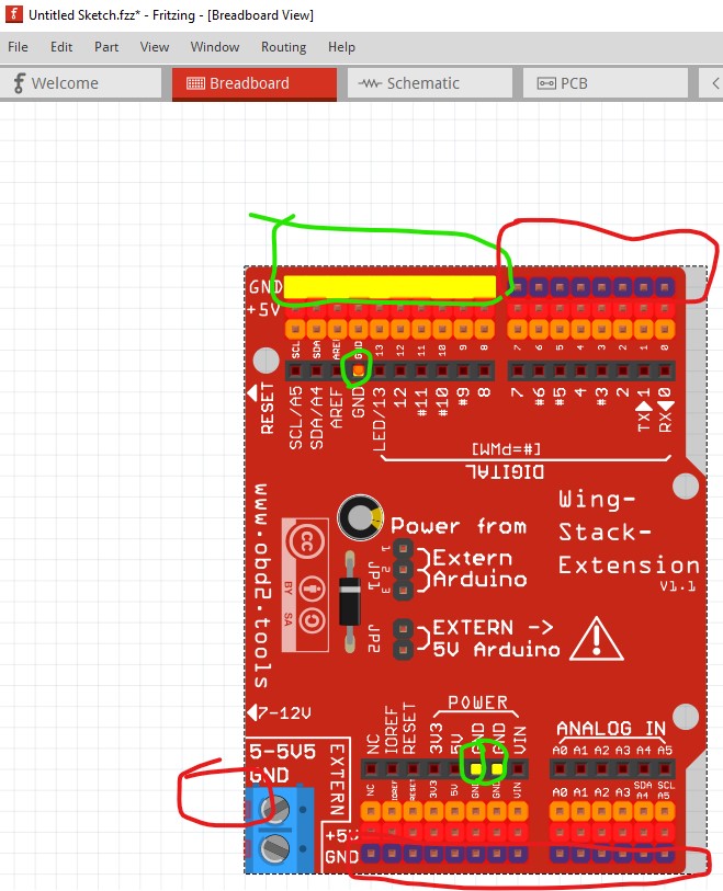
edit: Here is a slightly modified part which gives an example of the changes needed. Here I only added the top 10 connectors to the ground bus, the rest need to be done as well. All the rest of the pins that are connected together (and there are a lot of them!) also need to be in the bus definitions to make a proper part.
Note when I click on the ground on the arduino the first 10 ground connectors on the top also light up (as should all of the ground connectors circled in red!) To address the svg size issue I replaced the GND and +5V text items in circled in green here:
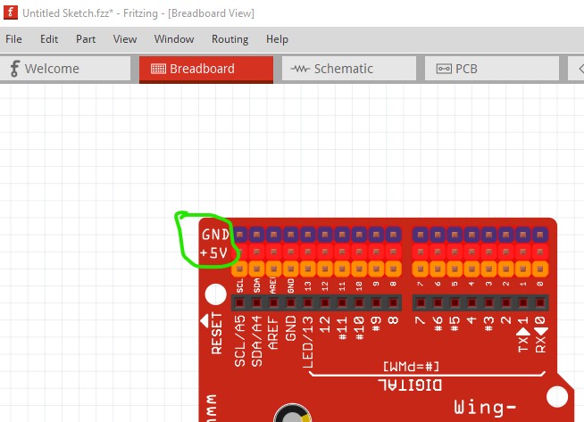
with a same size OCR font text string which will reduce the size of the svg considerably. I also adjusted the fzp file to use female connectors and the breadboard layerId to breadboard (from breadboardbreadboard which is not correct) and set that as the layerId in the breadboard svg. I also reused the breadboard svg for all the svgs cutting some 300 kilbytes from the part. Replacing most of the rest of the text with text instead of paths should reduce the size quite a bit more. Here is the modified part:
Wing-Stack-Extension for Arduino Uno-improved.fzpz (87.1 KB)
Peter
I must strongly disagree. Instead I will stay that people that only use one view have more limited needs than many others. Or maybe do not yet know enough electronics to use the other views. Each view has its purpose and reasons to use it. Fritzing is “tool”, and different people use it for different purposes.
As Peter, said, you are free to post any part you like. However, parts should include information about the any limitations. Like only being useful for a specific view.
And others are free to comment on the parts you post, to say when they are broken. Even if this had been described as breadboard only, it is still broken. Breadboard view is WRONG and INCOMPLETE. As described briefly in my post, and in more detail in Peter’s.