For the purpose of impedance matching and floating a single-ended, ground-referenced signal, I am planning to use an audio transformer like this one.
Here’s the schematic from the data sheet:
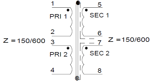
My source has 150 Ω and I am using an output impedance of 600 Ω. Therefore, I am connecting pins 6 and 7 and feed the secondary (5-8) into my 600 Ω load. For the source, there appear to be several options:
-
Feed the signal to 1-2 only, connect a 150 Ω resistor across 3-4. This will increase the power that has to be provided by the load, and the desired impedances cannot be achieved: 150 Ω source impedance matches 1-2, the additional 150 Ω resistor only appears to matches 3-4 but really messes up everything else, and the output resistor matches 5-(6,7)-8. -
Feed the signal to 1-2 only, leave 3-4 open. No additional power required for unused winding 3-4, impedances on 1-2 and 5-(6,7)-8 will match, but any parasitic capacitance across unused winding 3-4 might build a resonant circuit across this winding and degrade the fairly linear frequency response of the system. Might be a bad idea (?). -
Connect the two primaries in parallel. No additional resistor required, thus no additional power dissipation. Impedances on all windings will match: 150 Ω source impedance matches (1,3)-(2,4), and the output resistor matches 5-(6,7)-8. However, any possible mismatch between the two primary windings might degrade the performance. Mains (50/60 Hz) transformers that can be configured for either 115 V or 230 V are usually connected exactly this way to use the additional copper of the paralleled primary windings, but how about audio frequency transformers, where stray capacitance is a concern because (a) it is larger due to the high number of turns and (b) it matters more because we're using frequences up to 15 or 20 kHz instead of just 50/60 Hz?
Which option is preferred? Why?