I am currently involved in the project and I’m trying to understand why connecting,an arduino digital pin 4 to pin2 of a 2N4401 transistor vs 5V PSU to pin1 of 2N4401 transistor and pin 1 and Arduino VCC to 2N4401 pin 3, won’t keep power. When shorting pin 1 and pin 3 on the 2N4401 the MCU is powered on and in-software pin 4 is set to pinMode OUTPUT and HIGHwhich should allow the 2N4401 to let power flow to the MCU for as long as power is available even when the short circuit between 2N4401 pin 1 and 3 is cut.
I am trying to understand why connecting, say, an Arduino digital pin 4 to a 2N4401 pin 2 as well as 5V PSU to 2N4401 pin 1 and Arduino VCC to 2N4401 pin 3, won’t keep power.
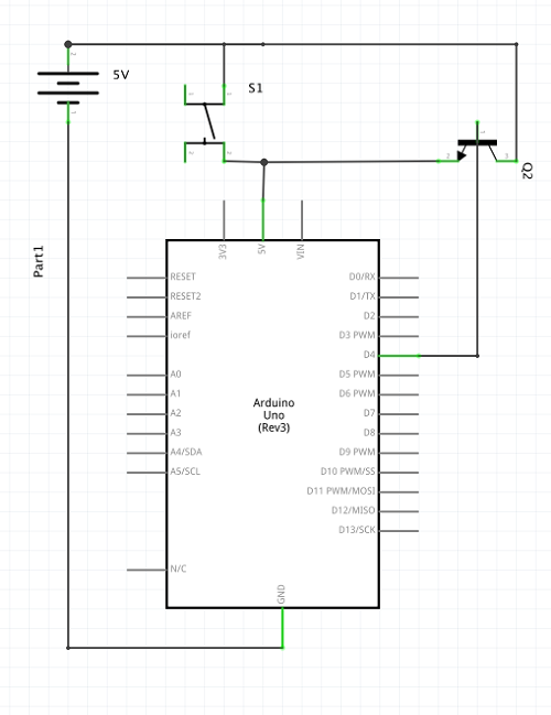
Just look at the folllowing picture:
Could anyone explain why this is happening?
I’m sure I lack a lot of knowledge here and I want to know how I could utilize a 2N4401 to make a SW shutdown system. The code is as following: void setup(){ pinMode(4, OUTPUT); } void loop(){
** digitalWrite(4, HIGH);**
** delay(3000);**
** digitalWrite(4, LOW);** }
Why 2N4401? Why not a MOSFET? MOSFET’s circuits that do SW shutdown are available, but no transistor base SW shutdown circuits are to be found anywhere, and the 2N4401 is all that I have right now.
When shorting pin 1 and pin 3 on the 2N4401 the MCU is powered on and in-software pin 4 is set to pin Mode OUTPUT and HIGH which should allow the 2N4401 to let power flow to the MCU for as long as power is available even when the short circuit between 2N4401 pin 1 and 3 is cut.Instead what happens when the short between pin 1 and 3 is cut, the MCU is turned off instantly.It’s as if the transistor isn’t reacting to the pin 4 MCU signal at all.(because of this question,i also find information form internet,and I find a valueful article name" What is 2N4401 transistor and how does it work" , however it didn’t give me a direct help so I hope someone help me here)
I think the simple answer is that you can’t. There are a number of things wrong with this circuit, starting with the connection of power to the 5V pin. The input power (greater than about 7 volts) should be going to VIN (assuming you don’t have the USB connected in which case the 5V is coming from the USB connection), the 5V pin is the output of a voltage regulator. You might be able to make a circuit where a PNP transistor connected across the power switch (assuming the power switch is a push button) was held on by writing a 0 to the D4 port. You would need to hold the switch down til the arduino boots and sets the port to 0 (and would need a resistor between the base of the transistor and the I/O pin to control the base current), but that won’t work if the USB is connected.
2n4401 is an NPN transistor. That means its emitter E goes to negative supply, and both collector C and base B must be more positive than E for it to conduct any current. The B-E path thru it is like a diode, needs ~0.5-0.7v to conduct, then it needs series-limiting resistor so it doesn’t conduct too much and burn out. When it does conduct, say, 1mA, then the C-E path opens a little and allows about 100x that current, I.E. 100mA. Assuming there is a largish voltage there, like +5v above E. And if there isn’t much voltage above E, then the current is much less and the C voltage bottoms out at ~0.2v above E. You can see that NPNs are not ideal switches. (MOSFETs are better).
One thing could be done: a voltage doubler to drive the NPN base above the 5v rail, then the NPN could turn on. To do that, D4 would need to be oscillated in software, at rates ~10khz.
Voltage doubler is:
capacitor 1uF, D4 to node1,
1n4148 diode, cathode to node1 & anode to 2n4401 E, 1n4148 diode, anode to node1 & cathode to node2, capacitor 1uf, node2 to 2n4401 E,
resistor 1k, node2 to 2n4401 B,
resistor 10k, 2n4401 B to 2n4401 E.
2n4401 E & C, same as you showed.
(Transistors often need a lot of small parts like those to help them do the right thing.)