I seem to be having some issues with exporting my parts into the editor. The following is a screenshot, of both the parts editor and the weird behaviour when dragging the newly ‘saved as’ part into the breadboard editor.
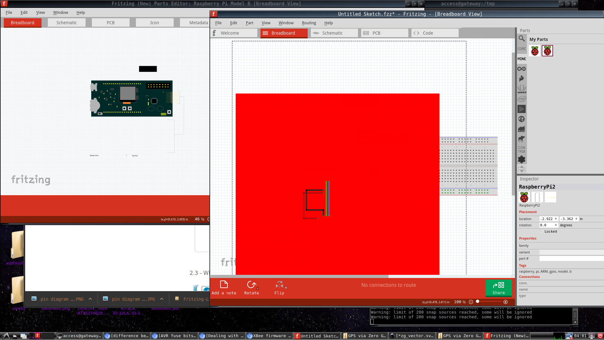
Any suggestions are welcome.
I seem to be having some issues with exporting my parts into the editor. The following is a screenshot, of both the parts editor and the weird behaviour when dragging the newly ‘saved as’ part into the breadboard editor.
Any suggestions are welcome.
Upload the .fpfz file here (upload is the 7th icon from the left in the tool bar just above where I’m typing this) by right clicking on the new part in the mine parts bin and clicking export part (which writes the fzpz file) and one of us will look it over and tell you whats wrong. Likely (because of the red background) is improperly specified connectors. You may also want to look at the two parts creation tutorials that I posted in a thread before this just now, but uploading the file will likely be the fastest solution.
Peter
zg.fzpz (39.5 KB)
Hey vanepp,
Thanks for the reply. I have uploaded the .fzpz
A problem with the connectors?? Oh ok… That’s… weird…
I really like the look of this program, but it appears hellbent on over-complicating what should be a fairly uncomplicated process. The documentation also doesn’t lend itself towards legibility.
Just a little background, I created this in Inkscape then exported as a plain.svg. I dragged a part into the breadboard editor, then pressed “Edit (new parts) editor”… I proceeded to import the .svg and things were looking ok (it did ditch a .jpg section that I had imported to inkscape, which was really annoying. Figured it would bundle it as part of the .svg) (it was a pin diagram)… Anyway, so I ‘saved as’ and it appeared in the ‘mine’ section.
I didn’t touch any of the connectors, or anything else.
Really, all I want is a simply visual representation of a wiring diagram with a nice aesthetic. I’m not exactly building full pcb’s with F-zing.
Appreciate you taking the time to have a look at this. Interested to know the cause here.
I have to agree the parts creation docs aren’t the best (most are for previous versions in fact). Both I and Old_Grey have had a bash at creating something but its still not great (and I’m still learning how to make parts from the more experienced folks here). Parts creation is complex, but that is the price we pay for being able to make connections that (more or less) match real life in breadboard. I too rarely make boards, I’m usually making one or two of something on perf board and Fritzing is about the only thing I know that will document that so I’m willing to invest the time to make parts. As to your part, yep, connectors are your problem. Your breadboard svg doesn’t have any  (thus the red square). You look to have started with the Raspberry PI GPIO board which does have pins in breadboard (as does your board, it just lacks the connectors associated with them). Your part appears to be a STK3200 development board of some kind and there doesn’t appear to be a Fritzing part for it yet (although you have made a good start I find getting a breadboard artwork image to be the hardest part of parts creation). If you unzip the fpfz file you will find these files in it:
part.STK3200_a74f05fc485b5c4f577e8d146594c9c2_2.fzp
svg.breadboard.STK3200_a74f05fc485b5c4f577e8d146594c9c2_2_breadboard.svg
svg.icon.STK3200_a74f05fc485b5c4f577e8d146594c9c2_2_icon.svg
svg.pcb.STK3200_a74f05fc485b5c4f577e8d146594c9c2_2_pcb.svg
svg.schematic.STK3200_a74f05fc485b5c4f577e8d146594c9c2_2_schematic.svg
svg.breadboard… is your breadboard file and the other 4 are still from the Raspberry PI GPIO card. The fpz file is your current problem as it contains lines like this:
…
< connector>
< connector name=“MOSI” id=“connector19” type=“male”>
< description>no description yet
< views>
< breadboardView>
< p layer=“breadboard” svgId=“connector19pin”/>
< /breadboardView>
< schematicView>
< p layer=“schematic” svgId=“connector19pin”/>
< /schematicView>
…
(note the above is butchered as the forum takes the real format as markup for the forum, so I added blanks that aren’t in the fpz file to fix that). Its happy with schematic view because that view is still the gpio and the pins match (thus the red bars on the connectors in schematic view). As you see above it has a line for breadboard view where it is expecting to find an element, typically a circle, line or rectangle depending on what type of contact you want,
in this case likely a circle centered on the pins, with the id connector19pin. When it can’t find that you get the red square (there are around 26 pins that it wants in the fpz file). To fix this you would need to add the ids to the pins on the board (as noted a circle with only a svgId=“connector19pin” will do for the ones that are ,025 pins, the ones on the right edge that look to be header lines are a little more complicated in that the line needs to be connectorxxpin and a rectangle out at the right end of the line (where a wire would terminate) needs to be terminalId=“connector0terminal” to define the endpoint of the connection (otherwise the connection will be in the center of the pin which won’t be what you want). Then you need to modify the schematic and pcb views to match the breadboard view so the same connectors appear in all three views (because Fritzing will with some limitations due to bugs reflect connections in one view in to the other two). If you have pin designations for the various connectors I can easily enough correct this for you (probably a lot easier than explaining how to do it in fact) which will give you an example of how to do it if you compare the final result to what you have now. With a full part you can wire your circuit on breadboard (and preferably, because of a bug, completely on breadboard or completely in schematic) and it will create a mess in schematic and pcb, which if you drag the parts to a reasonable position will display rats nest lines of the connections made in breadboard so you can make a schematic (and if you choose a pcb) from the circuit initially made in breadboard. You don’t have to complete schematic of pcb if all you want is the breadboard image but you do need the complete part for any of them to work. Once you have a functioning part, then you get to make the decision if the pain of making parts is worth the results you get from them (I find it is, quite a few folks don’t agree and move on to some other package).
Peter