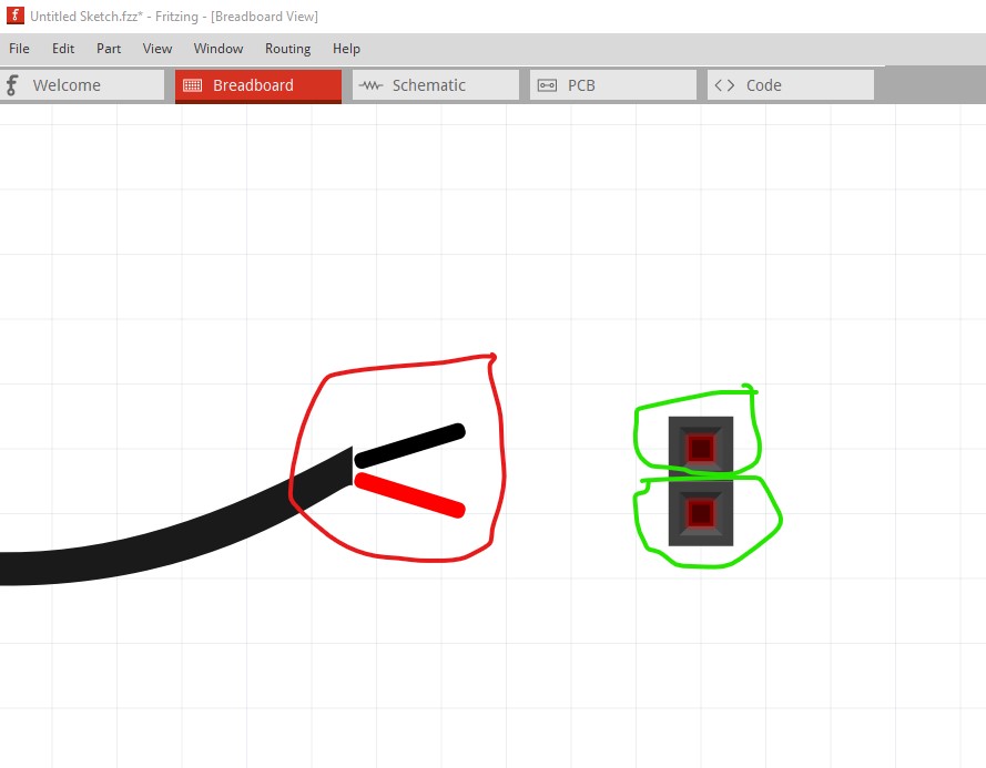
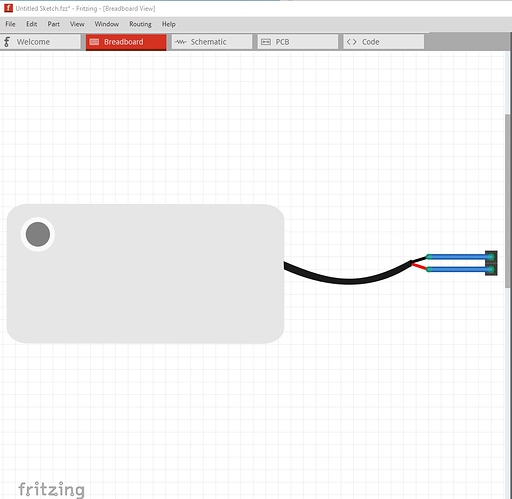
Not a bad job, but again a few problems. Breadboard lacks a layerId, and is dimensioned in px (although the scale is correct in both Fritzing and Inkscape despite that.) The motor part you cloned from is a bendable leg part and this one is not correctly configured for bendable legs so breadboard doesn’t work. This is your part in breadboard with a two pin connector beside it. Note the red squares in the header connector (which indicate active but unconnected connections.) Your part does not have such connections on the pins and thus won’t connect.
As before I ran your part through FritzingCheckPart.py and it generated these complaints (along with some more that are ignorable):
Warning 19: File
‘svg.breadboard.prefix0000_ad48e12d475048711e5902646654db99_6_breadboard.svg.bak’
At line 2
Height 114.22708892822266px is defined in px
in or mm is a better option (px can cause scaling problems!)
Warning 19: File
‘svg.breadboard.prefix0000_ad48e12d475048711e5902646654db99_6_breadboard.svg.bak’
At line 2
Width 337.2832336425781px is defined in px
in or mm is a better option (px can cause scaling problems!)
Error 69: File
‘svg.breadboard.prefix0000_ad48e12d475048711e5902646654db99_6_breadboard.svg.bak’
At line 9
Found a drawing element before a layerId (or no layerId)
Error 18: File
‘part.prefix0000_ad48e12d475048711e5902646654db99_4.fzp.bak’
Connector connector0leg is in the fzp file but not the svg file. (typo?)
svg svg.breadboard.prefix0000_ad48e12d475048711e5902646654db99_6_breadboard.svg.bak
Error 18: File
‘part.prefix0000_ad48e12d475048711e5902646654db99_4.fzp.bak’
Connector connector1leg is in the fzp file but not the svg file. (typo?)
svg svg.breadboard.prefix0000_ad48e12d475048711e5902646654db99_6_breadboard.svg.bak
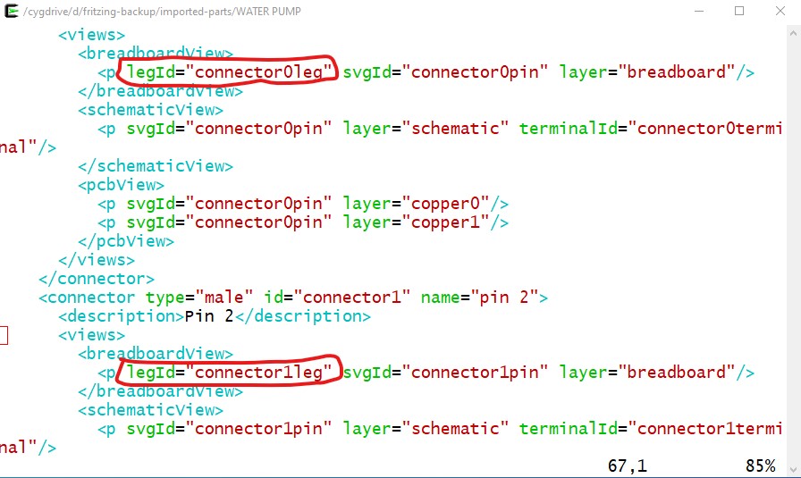
The last two are the indication that this was a bendable leg part to start with. To correct that you need to edit the
part.prefix0000_ad48e12d475048711e5902646654db99_4.fzp
with a text editor and remove the two legId statements (circled in red here):
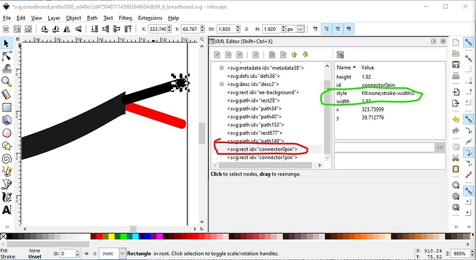
Then you need to add proper pins to the breadboard svg like this:
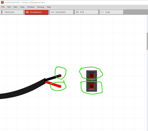
Here I created an invisible (fill:none stroke:none) rectangle the same size as the wire and positioned it on the tip of the wire. Then I duplicated it and moved it down .1in in y to make the other pin below it and skewed the red and black wires til they align with the new pins. Then I did an Edit->Select All, an Edit =->Resize page to selection, an Object->group then renamed the group to breadboard to create the layerId and recreated the part. Now in breadboard the pump has connectors which will connect to the two pin header and make the connection:
Note the faint red square on the end of the wires indicating a connection.
Now when I make the connections in breadboard:
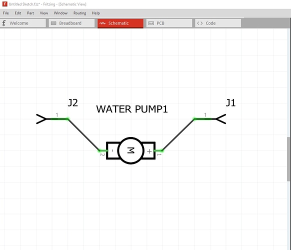
they reflect in to schematic and pcb as they should
Unlike your original part in the first image in this post which won’t connect in breadboard. Here is the fixed part:
WATER PUMP-fixed.fzpz (7.3 KB)
Peter
