Type
I did not read this
Breakout board, sub assembly, plug in module (A)
Antenna (AE)
Battery (BT)
Capacitor (C)
Diode (D)
Display (DS)
Fuse (F)
Hardware , mounting screws, etc. (H)
Jack, fixed part of a connector pair, header (J)
Relay (K)
Inductor, Coil, Ferrite bead (L)
Loudspeaker, Buzzer (LS)
Motor (M)
Microphone (MK)
Plug, moveable part of a connector pair (P)
Transistor (Q)
Resistor (R)
Thermistor (RT)
Varistor (RV)
Switch (S)
Transformer (T)
Integrated Circuit (IC)
Crystal, Oscillator (Y)
Zender diode (Z)
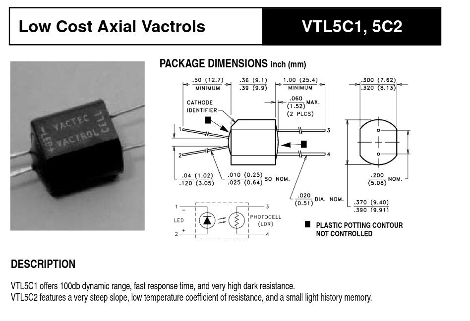
[ *] Other a combination of LED and LDR in one package.
This part should do what you want. Pcb is set for a hole size of 0.038in (the size for a 0.1in header) so you could plug the VTL5C1 in to a header if you want.
That’s brilliant! I don’t know what we’d do without @vanepp ! Thank you so much!
(EDIT, presumably we’d create really crappy parts ourselves, but that would not be doing humanity a favour
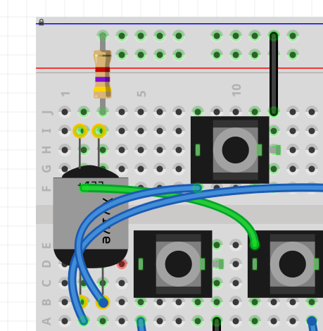
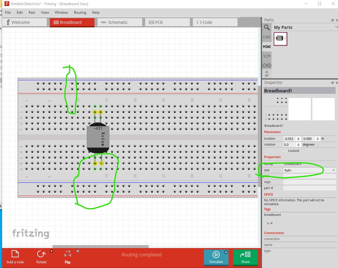
This is a Fritzing quirk (which I think is a bug, but the developers so far don’t agree), what is happening is Fritizng selects a pin (apparently at random) to align to the grid. Here on the full+ breadboard the power rail pins are aligned with the grid pins and all is well.
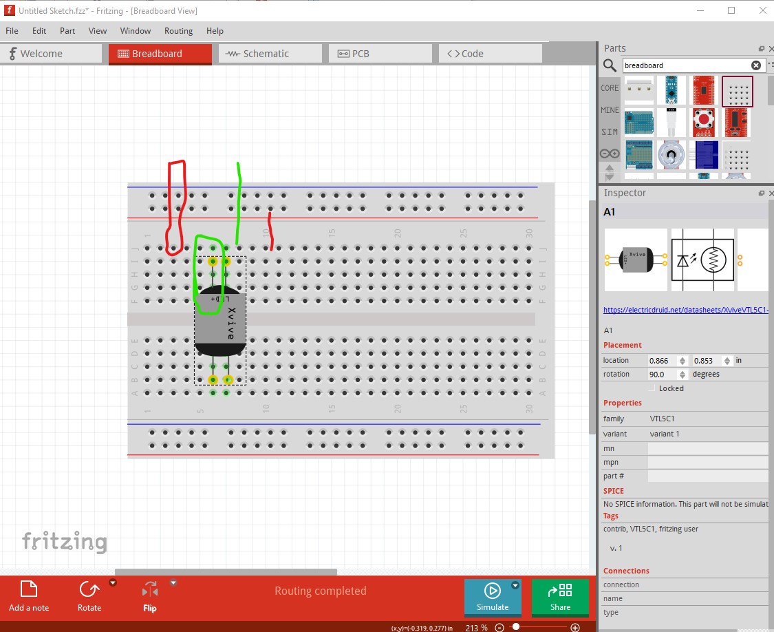
half+ breadboard (where the power rails are offset 0.05in in x from the main pins) it will at random select to align to the power rails producing a 0.05in offset in grid alignment. It does’t matter because connection has some amount of slop so it will connect. In this image the grid is aligned to the main pins. If I do this multiple times, sometimes it will align to the power rails and the main pads will be 0.05in offset from the grid. However that doesn’t appear to be what is happening in your case. I suspect
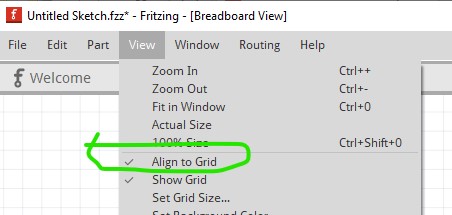
if you move the vtl part a bit it will snap to the grid (and you should check View to make sure align to grid is ticked because if it was not when the part was placed it won’t snap to the grid and this is then possible. That looks like what happened here as all the other parts are aligned to the grid correctly. and the power rails are not offset. If you have other parts that are misconfigured (with pins that don’t align tot he grid correctly) that can also do this if it chooses a misplaced pin as the grid reference.
Ah, thanks very much! I’ve played around a bit and they never quite align, but it really doesn’t matter. The PCB view (and resulting gerbers) are what matters and as long as connections are there in the bread board, it’s just cosmetic
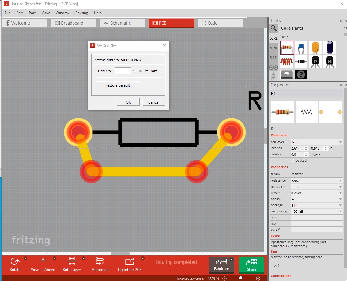
You can, just click “Set grid size” in the View menu in any view. The default is 0.1in but you can set any value (probably within limits) and click OK and it will change the grid size. Most useful in pcb view but works in any.
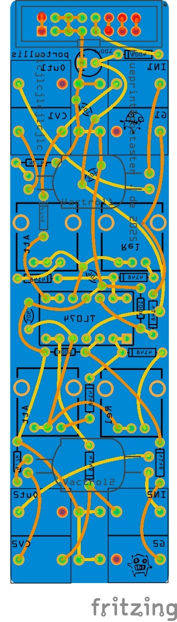
Yes, but it doesn’t go below 1 mm I have it set to the lowest value but, it’s an issue when doing stuff like top plates where pots come through and you need an aperture that’s really tight. 1mm is too course in that case. This is the top pbc for the above:
To date, I haven’t found a good way to make these and just make the holes too big and use pots (where I can) like alphas that have a fixing nut. With free standing trimmers, this is too ‘wiggly’.
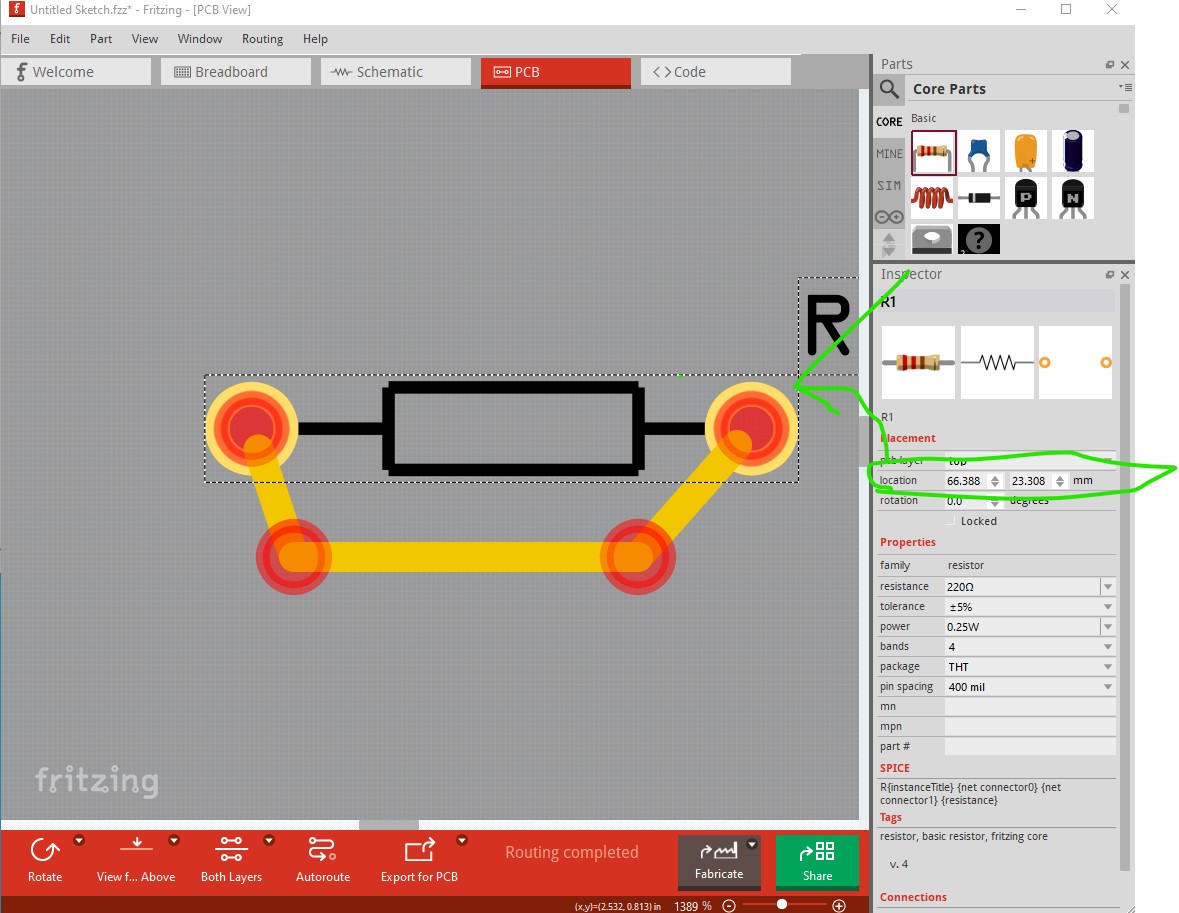
and part placement (via Inspector) will go even further down (although a bug was fixed in the last couple of versions the fixed this, it used to get bit by roundoff errors which made it not work unless you zoomed out.)
ah, I just updated to 1.0.4 and indeed it does. I wonder if I just had issues with an older version and didn’t try again? In any case, it does go that low in my 1.0.4 as well, so that should make my life easier Thanks!
In your receipt for the donation from Fritzing.org is a download link that will allow you to download updates for (I think) around a year so save that link.