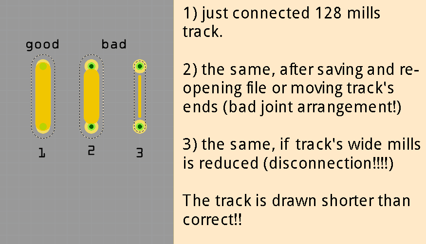
draw a track, and set large mills (e.g.128)
save file or move one terminal of the track
the track become shorter and a bad joint arrangement is made
if you reduce track width, the track can also become unconnected!!!
What I expected should have happened instead:
The track remain as drawn the first time. Please fix soon because Fritzing become totally unusable!
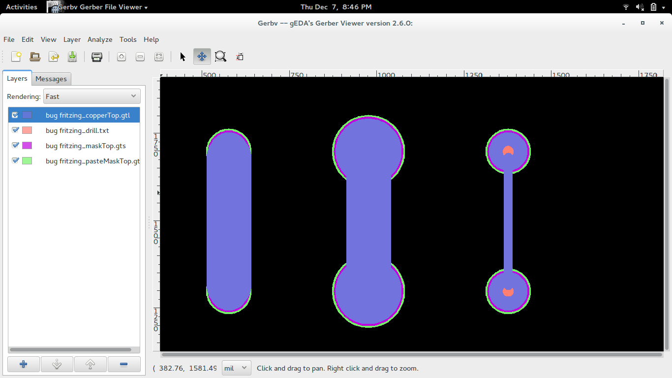
Although I have seen this once before I can not reproduce it now. Are you sure it is not just a rendering issue? Have you tried exporting the Gerber files and checking them in a gerber viewer? Also make sure you are using 0.9.3b not 0.9.3. If the problem is in the Gerbers after export have you tried dragging the wire connection off of the ring onto ta blank area, let go of it and then drag it again to the terminal it is to be connected to as this will cause the connection to be reset at the current track width.
Thanks for your attention
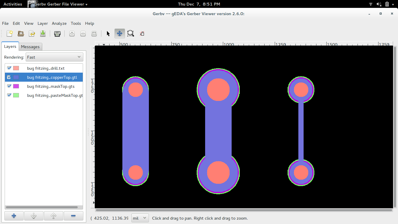
No, is not only a rendering issue. Also uploading to aisler.net or exporting to gerber (or any exporting filetype, svg, pdf) the problem is still here.
I’ve downloaded Fritzing few weeks ago from fritzing.org, so I think is the very latest release.
I downloaded your file and all three looked like your #2 example. When I changed the trace size it made it look like #3. To fix it I changed one of the VIAs ring sizes and then changed it back and the trace self corrected.
Development of Fritzing has staled for the last almost year now so a new release with this fixed is a long ways away. So my suggestion to you is to avoid making giant traces and then making them smaller later. If you do this for some reason you can work around the bug by changing the part it is connected to in the inspector and then change it back.
I hope this helps. There are a few of us that are trying to get development going again so all hope is not lost in getting another release but it will not be as soon as everyone would hope.
Thanks to all
My real problem is not to enlarge and stretch traces, but to have good shaped large traces. So the problem is still here: there are no way to save a file with large traces and correct & “beautiful” joints because the trace’s end seem to be too far from the centre of the pin/vias.
On the side of the code, unfortunately I cant’ help practically, because I’m totally ignorant about coding, but I think that the “logical problem” of the code at the origin of the bad render can be the location of the round cap of the trace, that must be put on the same location of the pin/vias, and no more exotically calculated.
(BTW, why complicated rounded cap if a trace always terminate on a round ring/vias/pin? perhaps this buggy part of the code can be simply removed to fix all the problems…)
I hope some code-expert can fix this because like this Fritzing is totally unusable for PCB with large tracks.
I think I submitted the round ends and other end bugs a long time ago, but unfortunately it didn’t get fixed in 9.3 so I had to use tricks, or just ignored it and put a lot of solder on the pin/trace to increase it’s current capacity.
I honestly believe if you are coming across this bug you are using too small of rings for the size of the trace. That is to say the ring needs to have at least as much copper around it as the trace is wide. So for a 128mil trace you need a 2mm ring otherwise your trace capacity is greater than the ring capacity which would defeat the purpose of using large traces.
Here is your sketch with the rings set to 2mm on the middle example and you will see it opens just fine and doesn’t need any workarounds. bug fritzing.fzz (1.7 KB)
I would also like to say using that size trace is rarely needed unless you are dealing with high currents.
Also I believe the round ends on the traces are there so where two traces meet each other and form a corner you get a round corner not a sharp noisy corner.
I think the way Fritzing connects the end of a trace to a ring is to connect the center of the circle used for the end of the trace to the center line of the ring not the center of the hole. If that is the case I would imagine it would be a trivial change to make in the code if one were to know where to look.
I will try and poke around a little to see if I can find it.
If you do not have room for a larger via then do you need that large of a trace? The copper area in the hole of a via can not be equal to a 128mil trace, can it?
After a few tries I managed to find where it calculates the trace length for each type of pad/ring connection point in the source code. They were subtracting half of the trace width from the length if it was connected to a ring. I simply removed this bit of math and now the rounded end starts in the center of the hole. With smaller traces it looks a little ugly in the renders and could cause an issue with home etching if you rely on the copper divot to center your drill.
I actually home etch, and to center the drill I go to the pain of putting a 0.004" via on each pad because the usual 0.038" allows the drill to wander. Any chance you could keep the subtraction, but make it half the drill hole.
That is a good way to calculate it … but not easily for me. Currently it does not pass the hole diameter to the function that clips the path lengths. I believe it is relatively easy to pass it that data but I do not understand object oriented programming very well so it is not automatic for me.
I’m still studying things. I have found in the gerberexport how it deals with drill holes so now if I can figure out how to use that data in the trace clipping function we would be set.
Wow!
Many thanks for extra-fast (and “magic” for me!!!) resolution of this problem!
Is the src/items/clipablewire.cpp modification replicable on a current installation (it’s a script I can change on my pc), or I must wait for a new full build of Fritzing?
Unfortunately it has to be compiled and built so It is not a change you can make on your current running system. This does mean having to wait for the next release.