Hello everyone,
for my next PCB project I’m looking for a vertical USB-C receptacle. USB 2.0 is perfectly sufficient. In Fritzing and via Google search I can only find right-angle USB-C receptacles. Has anyone already made something like this and could make it available to me? Or even create a new part? In my opinion, the Molex type 217182-0001 would be very suitable. Here is the link to the component and the datasheet: 217182-0001 Molex | Mouser Deutschland
actually, you could use a different USB socket and change the footprint as well as the schematic symbol. I had already read out the footprint. Unfortunately, the dimensions look different from those in the datasheet.
Do you have a way to verify the dimensions using the datasheet and an original part? I’ll try to find a mistake I may have made during the export.
Hello Harald,
thank you for your support.
Where can I see what you have read out? Where can the dimensions be found? Is there a file? Can I import it into Fritzing? I would like to compare your dimensions with the original part. I am also happy to order the USB sockets.
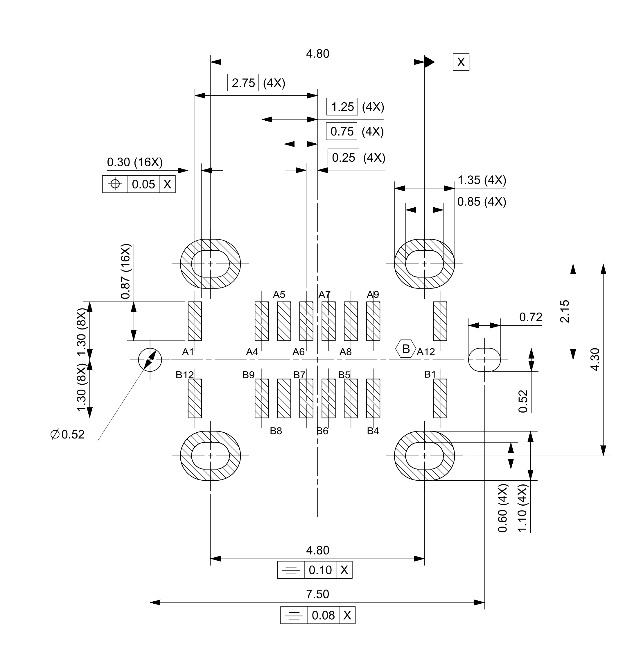
the dimensions are in the datasheet. I’ll upload the dimensioning again here.
You also want to create a PCB with the socket, so that the socket can be soldered onto the PCB afterwards. Because then the values have to be exactly right.
Hello Harald,
the suggested GCT socket is unsuitable, as it is only designed for power transfer / charging purposes. I need a socket with data transfer capability with at least USB 2.0.
No socket has been purchased yet, we are happy to go with a different one.
You’re right, the GCT USB4960-00-C is the same as the Molex one. I’m only comparing it in detail now. The footprint of the GCT USB4960-00-C or the Molex 217182-0001 would still be my favorite. The alternative models were only meant in case it makes things easier for you.
I don’t use the breadboard function. So the symbols are not relevant to me.
…it does take some time. I first need to deal with the holes for the mounting. I’ve never done that before…\n\nI’ll try it first for the Molex 217182-0001!\n\nBest regards, Harald!
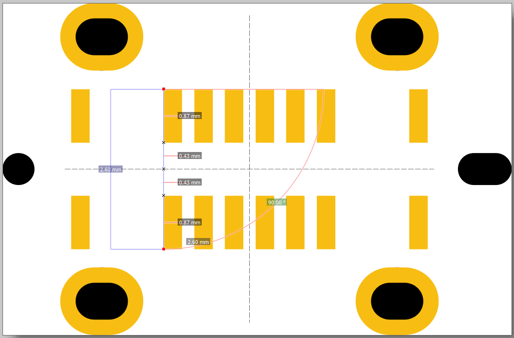
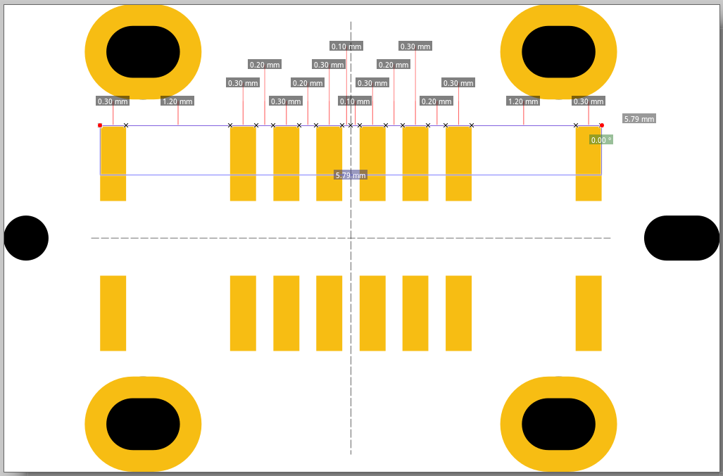
I am currently trying to create a footprint for a USB socket. I was able to import the footprint file, but some of the dimensions are not correct. They deviate by about 0.01 mm. Unfortunately, the mounting holes are also wrong. I have to redraw them.
Can you please tell me if I am on the right track.
I will then replace the mounting pads with the inserted oval and check the dimensions carefully.
Good news. Mouser was quick and already delivered today. Instead of the planned GCT USB4960-00-C, I accidentally ordered the GCT USB4235-03-C. It differs slightly in footprint. Specifically, it only has one mechanical mounting on each side. Otherwise, it would also be fine for me. Maybe that simplifies things. Here’s the link: USB4235. The Molex, which remains my favorite, arrived as planned. So I’m already ready for testing.
Now I just need to adjust the SVG file so that Fritzing recognizes the holes and also passes them on for drilling. I’ve never done that before and it will take some time.
Luckily the Easter eggs are already hidden, so I’ll give it a try this week.
I’ll take a look at the second variant as well — the left connector only has two points for soldering, right?
Good morning,
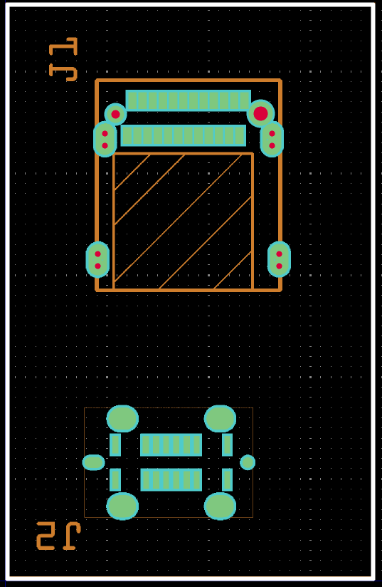
I have now tested the old version first and “came a cropper” with it. The holes are not being drilled. I saw this with a Gerber file viewer.
However, I do have a part where it works (see image). I want to examine this part and find out how Peter did it. I also asked the question in the forum, but everyone is very busy there.