This is just a question to confirm if I’ve read the spec right.
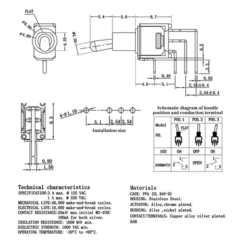
It appears to me that I could just place a 5 pin header for this part (with one extra hole unused). Am I reading this right? Thanks for helping the near sighted ! ![]()
This is just a question to confirm if I’ve read the spec right.
It appears to me that I could just place a 5 pin header for this part (with one extra hole unused). Am I reading this right? Thanks for helping the near sighted ! ![]()
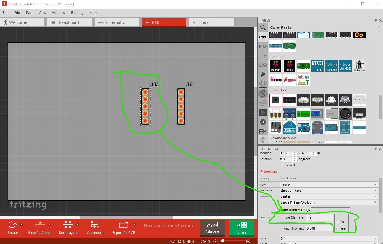
Yes but … You would need to increase the hole size on the header. By default it is 0.038in for 0.1in headers, but this is calling for a 1.10mm hole which is 0.043in. So you need to increase the hole size of the header in inspector to make it 1.1mm like this
which results in a gerber drill.txt file like this (new header / standard header)
; NON-PLATED HOLES START AT T1
; THROUGH (PLATED) HOLES START AT T100
M48
INCH
T100C0.038000
T101C0.043307
%
T100
X024222Y013222
X024222Y014222
X024222Y012222
X024222Y011222
X024222Y015222
T101
X019222Y011222
X019222Y015222
X019222Y013222
X019222Y014222
X019222Y012222
T00
M30
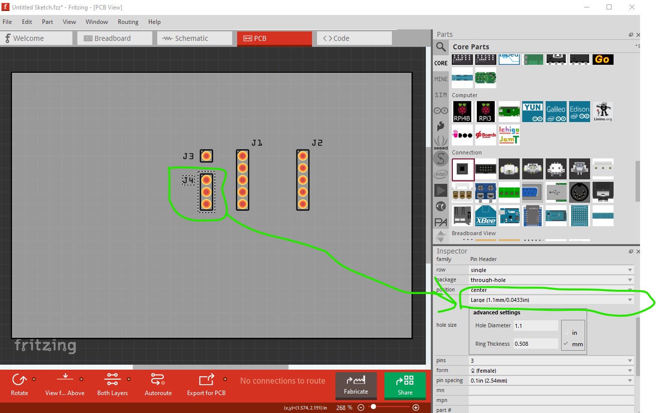
To make a more accurate footprint you could use a one pin header and a 3 pin header spaced 0.2in apart to make the exact footprint without an extra hole. Here I got lazy and used the large size hole rather than specify a custom size.
Peter
Ok, i wasn’t sure about the 4-01,10 → ← bit but you’re reading 4 times 1.1 mm. makes sense. Otherwise, the spacing should be exact with the ‘Installation size’ at 5.1 + 2.54 + 2.54 with a 5 pin header, or?
Thanks for looking!
To match the data sheet exactly the pads would indeed need to be custom. However there is some slop in the hole size for clearance so in practice the headers on 0.1in boundaries should work fine. To be sure print out the pcb footprint at 1:1 scale and compare it to a real part.
Peter