Basic circuit for a ESP8266 and Neo pixel (7 leds). Unit works well on a breadboard and thought I’d try my hand at a pcb, I willl have 5 of these to do.
Can I get some feedback? Very new to electronic circuits
Basic circuit for a ESP8266 and Neo pixel (7 leds). Unit works well on a breadboard and thought I’d try my hand at a pcb, I willl have 5 of these to do.
Can I get some feedback? Very new to electronic circuits
You need to upload (upload is 7th icon from the left in the reply menu) the .fzz file for the sketch with pcb done. A screenshot isn’t much use in looking over a design.
Peter
Sorry, here you go, thanks for the input!
Final.fzz (40.6 KB)
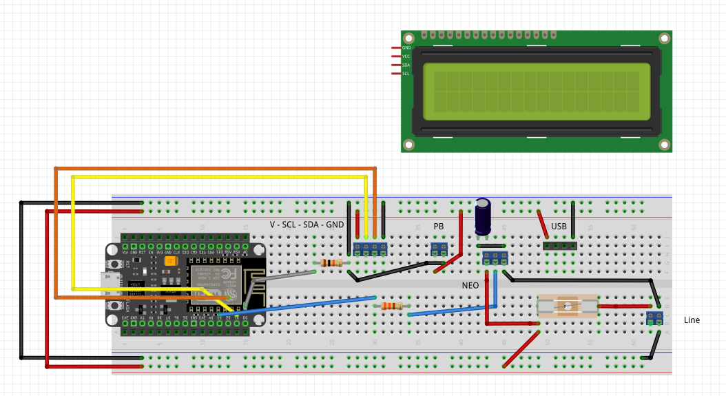
A few suggestions. You need to provide power to the node MCU, it is currently unpowered and thus won’t work. You need to connect the node MCU so the connections reflect in schematic an pcb to insure it is correctly wired. You need to add a neo pixel part and connect it to insure the connections are correct. In general it would be advisable to move the connectors off the breadboard and connect them to the part pins with wires so you can see where all the connections go.
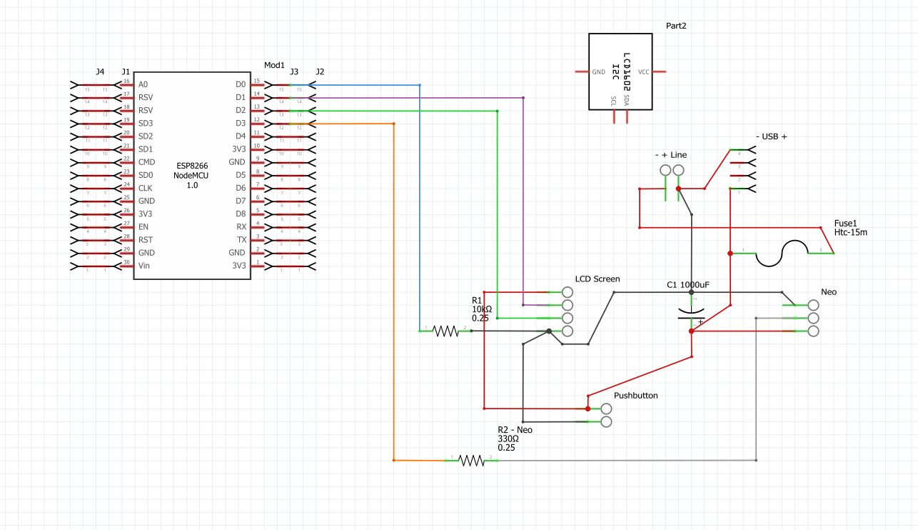
It is unclear to me how the LCD should connect to the node MCU as the connector order doesn’t match the LCD (and it probably should for ease of correct installation!)
Peter
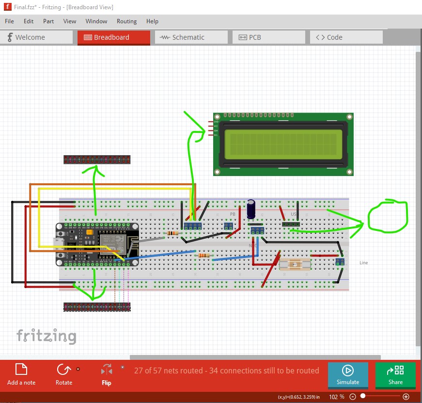
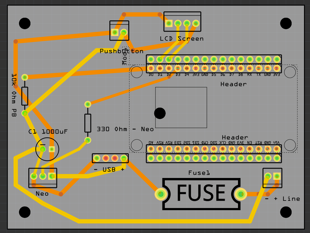
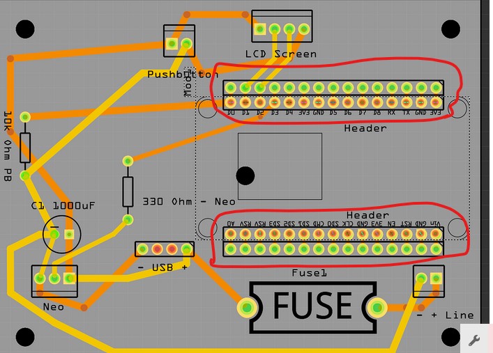
Yes, I disconnected the wires on the breadboard view as I am connecting through the screw terminals later. Hopefully this image helps explain better. The circuit does work, I was just wondering how electrically “sound” it was log term. I also keep moving components on the PCB the more I look at it. As you see in the second image, mocing the ESP in place gives me ratsnests that I didnt want to view while messing around with it
Oh, and the USB is to connect the ESP, power only
In general rats nest lines indicate a connection that needs to be made to match the circuit in breadboard and schematic (the rats nest lines reflect across all three views.) All three views should be identical and all the rats nests should be connected to insure success. As noted there is no evident power connection to the nodeMCU (unless the USB cable is connected to it) and there isn’t a ground connection evident to the rest of the circuit (which means it won’t work as the mcu signals don’t currently have a ground reference.) As well there is currently no connection (the red circles on the headers should be green if they were connected) on the headers in your diagram.
your Frtizing sketch needs to reflect real life before any useful comments on the circuit can be made.
Peter
Hi all, the ESP will be placed on the headers and the USB will be connected from the USB to micro usb on the ESP. The board is powered via the “Line” connection. I will try to incorporate all the components when I can get back to a computer. I assure you the circuit works as intended.
I had orginally removed the esp from the circuit to eliminate the confusion. I will post a new file later this weekend! Thanks for the feedback. Sorry about the confusion