Ich habe das Problem, dass ich ein Projekt auf der Steckplatine zusammengestellt und verdrahtet habe, im Reiter Schaltplan oder Leiterplatte fehlen aber die meisten Verbindungen.
Mache ich etwas falsch?
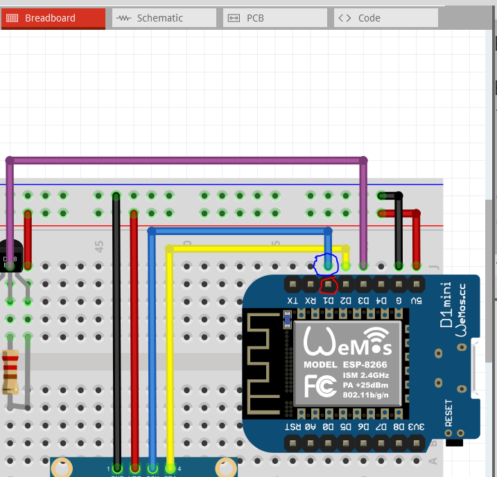
If you look at the connection D1 on the D1 mini board the blue circled wire with the green connection is connected (you can tell that by clicking on the wire and everything connected to it will light up in yellow, which does not include the D1 mini pin as it should!) The mini pin circled in red has no red (not connected) nor green (connected) circle and is thus not connected to anything and thus doesn’t show up in schematic. Here I moved the D1 mini down on the breadboard and connected it with wires which connect correctly:
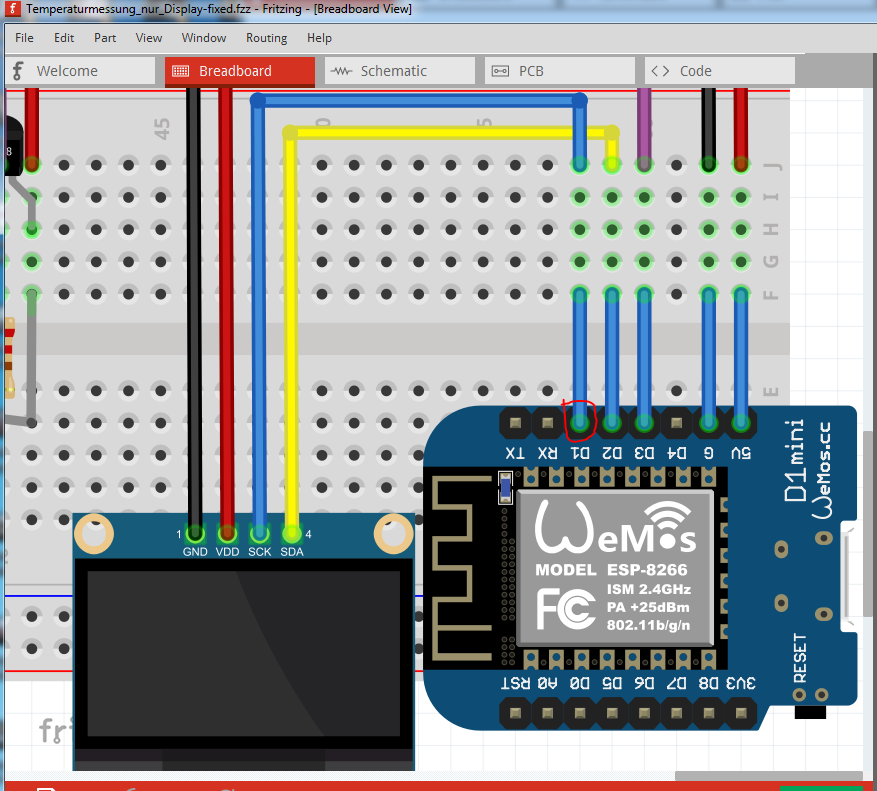
As we see there is now a green circle (indicating a connection) on the D1 mini pin and the connections show in schematic as they should. Here is the sketch the above is from:
Wenn Sie sich die Verbindung D1 auf der D1-Minikarte ansehen, ist das blau eingekreiste Kabel mit der grünen Verbindung verbunden (Sie können feststellen, dass durch Klicken auf das Kabel alles, was daran angeschlossen ist, gelb leuchtet, was das D1 mini nicht enthält Pin wie es sollte!) Der rot eingekreiste Mini-Pin hat keinen roten (nicht verbundenen) oder grünen (verbundenen) Kreis und ist daher mit nichts verbunden und wird daher nicht im Schaltplan angezeigt. Hier habe ich den D1 mini auf das Steckbrett gelegt und ihn mit Kabeln verbunden, die richtig angeschlossen sind:
Wie wir sehen, befindet sich jetzt ein grüner Kreis (der eine Verbindung anzeigt) auf dem D1-Minipin und die Verbindungen werden schematisch angezeigt, wie sie sollten. Hier ist die Skizze, aus der das Obige stammt: