Here’s an issue I’ve run into. I have a decoupling capacitor between the main power source (component A) and power/ground of the component I’m powering (component B). When I run the ground fill process, the ground pin on component B connects directly to the ground fill and not the capacitor. The grounds on components A and B are identified as GND in the ground fill seeds list, so toggling it turns all of them on or off.
What I think I need to do is make sure that ground from the power source hits the capacitor before ground on component B. But how can I go about this? Thank you!
While I know little about ground fill, I believe it is the shotgun approach i.e. it fills everything. If you want a specific path, try putting a trace to the point you want before doing the ground fill. You might also upload the sketch (the .fzz file) via the 7th icon from the left on the reply menu so we can see what you are talking about.
I needed to take my motor-driver from breadboard to PCB. It’s a simple enough design (very commonly used) and I no longer wanted to dangle them from wires.
I was in the middle of doing it when I saw this post - specifically regarding Copper Ground plane.
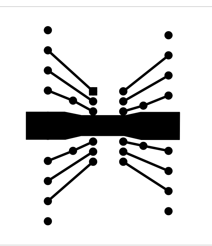
The Fritzing gnd plane is cumbersome so, when needed, I use the “Copper Image” part and load my SVG.
Works well for my projects so, I thought I post response…
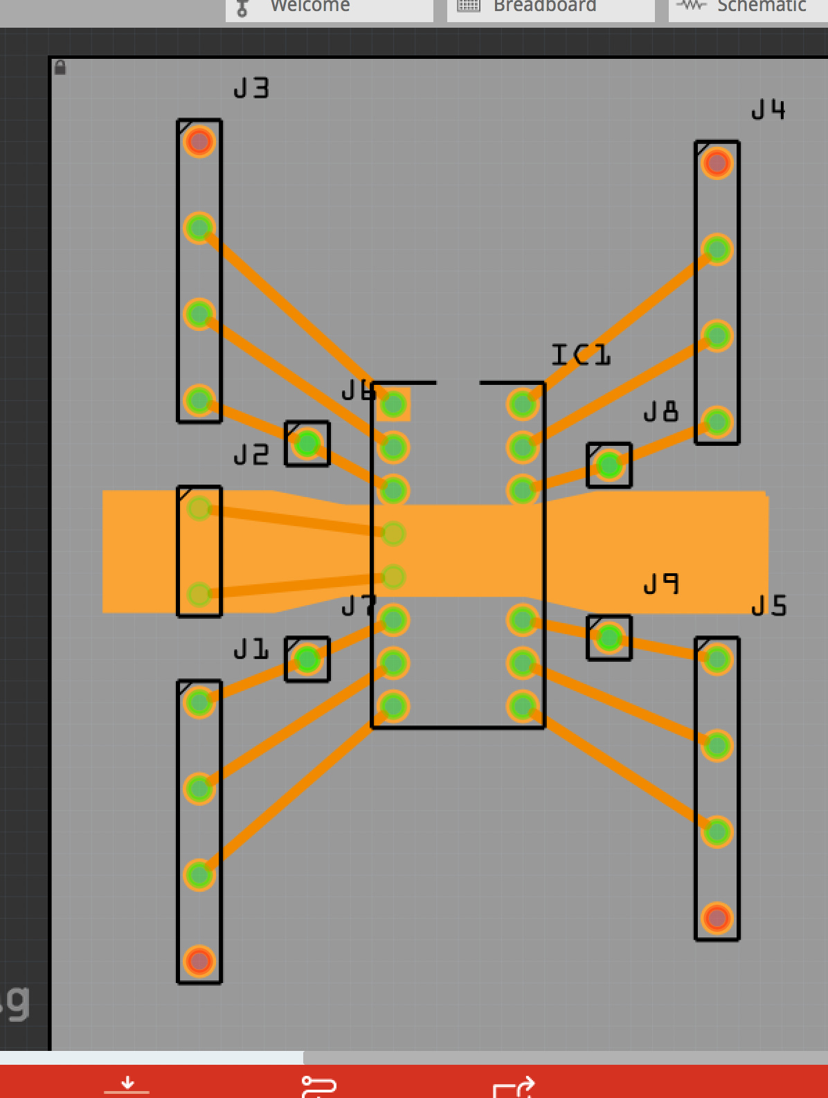
I just started this and it’s only roughly designed but it’s enough to convey the concept. (will finish it soon).
Image tells it all…
The SVG of the gnd-plane
The gnd plane lays under the 4-gnd pins (will extend to second H-bridge chip)
The two traces will not be needed as the plane will be in contact with each chips 4 gnd pins. The plane is intended to help dissipate heat.