I have a SRD-5VDC relay part in Mine bin. I have updated the pcb SVG file to place silkscreen around the part for the PCB and then created the fzp file with the updated SVG. When I go to import it, Fritzing gives an error about the part already exist. Do I have the delete the existing part before I can import the updated part?
Yes. The new part has the same ID as the old so it thinks it’s a duplicate. You can change the ID #s in the .fzp file, or you can delete the old file in - C:\Users\X\Documents\Fritzing\parts\user -.
Am I correct in that changing the moduleId in the fzp file does not impact the name of the SVG files?
Also, the current modelId has a 34 char alphanumeric in the value. Is this required or can I have a moduleId of something like srd-05vdc-sl-v1?
If this is an updated part of one you created that is in MINE bin, delete the file, other wise you can change 1 character in the ID, or cut all the odd ball characters out, just do what you want, but make it consistent in all the IDs.
Don’t be scared to try stuff and learn how it works.
I’m confused… when I look in fritzing\parts\svg\user\pcb\xxx.svg, I have the edited SVG file:
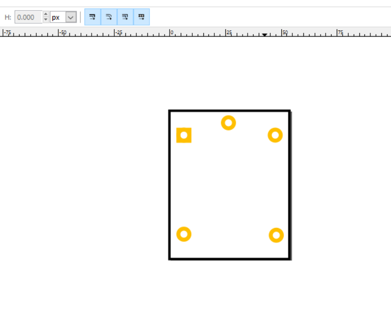

It has a black box defining the silkscreen on the PCB for the relay. When I click on the part in Fritzing, the PCB thumbnail shows the black box. But when I place the part on the PCB, I don’t see the black box:
Untitled Sketch.fzz (11.9 KB)
So I’m clueless what to do next 
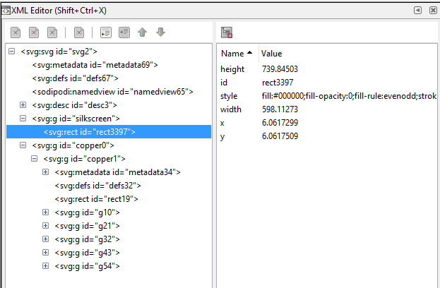
In Inkscape open the svg, and then open the XML Editor…
The rect3397 has to be in a group called silkscreen. In PCB view all holes and contacts are in copper, like you have, and all outlines and text go in silkscreen.
Top of the editor select New Element node, type in svg:g, OK.
Click on that new group node, and then click on the id in the right pane.
At the bottom of that pane is another box, change the id to silkscreen and press Set, just above it.
Use the arrow keys to move the silkscreen above the rect3397.
Select rect3397 and press the Indent button, top toolbar,
Now select the silkscreen again and move it above the copper groups.
In PCB view all holes and contacts are in copper, like you have, and all outlines and text go in silkscreen.
I don’t know what that .fz file is so you will probably have to get rid of it before importing into FZ
Old_Grey, thanks… even I understand those instructions
I believe I’ve followed your steps as you defined them and here is the modified XML file:
The PCB image still does not show the silkscreen box. Is there something wrong with the XML?
You are missing the layer “silkscreen” in you .fzp… Your file reads;
  </schematicView>
  <pcbView>
   <layers image="pcb/srd-05vdc-sl-c_89928e70ece586936e47c224e4f62621_1_pcb.svg">
    <layer layerId="copper0"/>
    <layer layerId="copper1"/>
   </layers>
  </pcbView>
 </views>
 <connectors>
It should read;
   <layers image="pcb/srd-05vdc-sl-c_89928e70ece586936e47c224e4f62621_1_pcb.svg">
    <layer layerId="copper0"/>
    <layer layerId="copper1"/>
    <layer layerId="silkscreen"/>
</layers>Thanks Steel, that one had me scratching my head.
There couldn’t see anything wrong with the svg, so I was thinking the .fzp file.
Again… that’s why you’re Mr. Fritzing
Success!!!
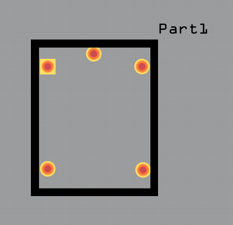
As you can see the line of the box is a bit wide but I think I know how to fix that situation
Here is the new version with the silkscreen on the PCB… many thanks to Old_Grey and Steel
songle relay.fzpz (10.9 KB)
I try to teach as many people as possible, as opposed to doing it for them, to advance FZ by getting as many people making parts as possible, so good work.
I noticed you will have to tweak the Breadboard because 2 connectors don’t connect to the BB.
Another tip is always set a 0.100" grid, so when you make stuff it will line up with stuff right from the get go.
EDIT
Is this the correct datasheet for the part, because I ran a ruler over it and some of the dimensions need tweaking.
Sorry to add more work but the PCB has to be deadly accurate for production, or things won’t fit or will foul with other parts.
Old_Grey… I’m not the original author of this part. I found it on the Internet and updated it to include the PCB silkscreen so I’ll have to check the dimensions of the pins.
Check the part you have because I see the top and 2nd row of contacts are 1.4mm compared to 2mm - 0.6mm out -. You may be able to force it, so you might get away with it.
I tweaked the part to the datasheet. It must have been some Eagle convet, because there was a lot of unneeded stuff.
songle relay-v2.fzpz (10.9 KB)
Many thanks for tweaking the part for me… did you change the part name so it can be imported or do I need to delete the existing part?
Opps, I saved it as the original part so you will have to delete the old part.
C:\Users\X\Documents\Fritzing\parts\user
You could also unzip it and load the PCB and Breaboard svg into your part, during an Edit, and set graphics for connects in PCB.