I ran that part through FritzingCheckPart. Here is a summary of what it reported.
For the pcb view image.
The new convention is to use black graphics for pcb silkscreen, instead of white. Fritzing automatically converts (and so does the FritzingPartsCheck tool), but for future reference, black is preferred in the pcb svg files.
The copper0 layer should be ‘inside’ the copper1 layer, instead of the other way around.
To make selection easier, the silkscreen layer should be above the copper layers. That is silkscreen should be at the beginning of the file.
FritzingCheckPart does not report this, but from manual inspection of the files, I see that you have keepout, soldermask, outline layers shown for the pcb view. Those currently have no special function implemented, but if specified, they should exist in the svg file.
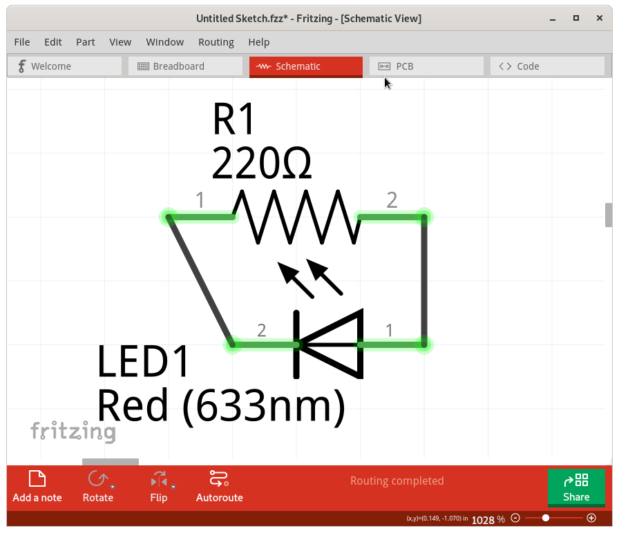
For schematic view image.
FritzingCheckPart reports that the terminalId attribute references (connector«n»terminal) will not work on “g” elements. They need to be on the actual graphical element. The polygon in this case. However, in my quick test, they seem to work just fine. @vanepp , do you have a sample for a case where terminalId on a schematic group element causes a problem? In this example, the group has the id, and contains a single polygon element. Which seems to work correctly. Maybe it only fails with more complex graphics in the group? Or no graphics, if the group was attempting to have a coordinate location but no actual content?
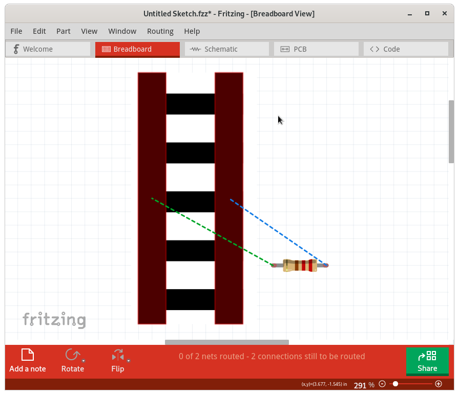
For breadboard view image.
The breadboard svg image is missing the layer id wrapper, which should be on the first (and outer) graphical element in the file. The part will still work in Fritzing without the layer id, but it will not export to svg images.
Here is the problem that is similar to my initial guess. The breadboard view of the connector pin definitions have legId attributes set, but the specified “connector«n»leg” id values do not exist in the svg file. Those are for bendable legs on the part. They are optional, and the parts editor does not handle them. When a legId is defined though, that is the location that Fritzing uses to connect (draw a wire) to the part. Since that id does not exist in the svg, it has no graphical coordinate, and you get the symptoms you saw.
As a quick test, I manually (with a text editor) added the breadboard layer to the svg file, removed the legId references from the definitions, then recreated the part. The alternative would be to get proper leg graphics into the breadboard svg file, but doing that needs a little knowledge of where the legs should go. The existing graphics and connector information does not make that obvious.
% diff part.a_8954d5037939dc0adfd63ca8db8b9371_2.fzp.bak ../unpack/part.a_8954d5037939dc0adfd63ca8db8b9371_2.fzp
57c57
<      <p svgId="connector0pin" legId="connector0leg" layer="breadboard"/>
---
>      <p svgId="connector0pin" layer="breadboard"/>
72c72
<      <p svgId="connector1pin" legId="connector1leg" layer="breadboard"/>
---
>      <p svgId="connector1pin" layer="breadboard"/>
% diff svg.breadboard.a_8954d5037939dc0adfd63ca8db8b9371_2_breadboard.svg.bak ../unpack/svg.breadboard.a_8954d5037939dc0adfd63ca8db8b9371_2_breadboard.svg
16c16
<     <g  transform="translate(-93.243545,-96.935114)">
---
>     <g transform="translate(-93.243545,-96.935114)" id="breadboard">
test_a1.fzpz (6.0 KB)
My new sample part has the same Id as yours, so you will need to delete the old one from Fritzing before this will load. Or just continue working with what you have, using my notes.


 Get and learn to use the FritztingCheckPart tool. It did most of the grunt work. The rest was just a bit of experience with the way parts can be broken. As the diff showed, the actual fix was to delete 2 legId references, and add 1 breadboard reference. It would have worked without the breadboard reference. FritzingCheckPart directly told me about the legId in the fzp but not in the svg, so I just needed to search the svg to see if it was really missing, or just a spelling difference.