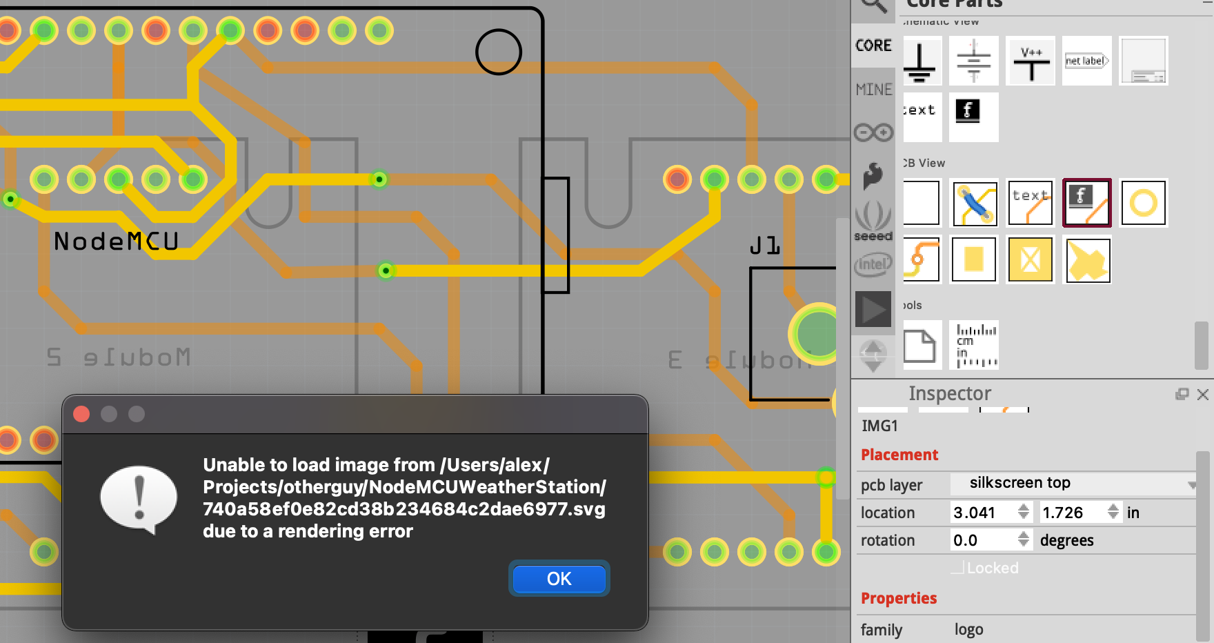
I’m using Fritzing Version 0.9.4 on macOS and I’m trying to place an SVG image on the silkscreen layer of my PCB. I’m fairly sure this exact image worked in the past but weirdly enough I can’t get it to place ANY SVG or PNG image now.
Every image fails with “Unable to load due to rendering error”:
That SVG image does not have any physical dimensions. Fritzing requires that to be able to scale the image to match the reset of the PCB graphics. To get it to work, I changed the svg header from:
The 1 inch references were arbitrary. I do not know what size the graphic is supposed to be. 1 inch means that the “1000 1000” viewbox values come out to mils.
I do not see any clues in the svg file about what tool was used to create it. Any that I know about would have included some sort of length and width values, even if they were in pixels. Pixels are not good, because translation from that to real world units is not consistent.
Fritzing is the only one that needs to know real world dimensions. To render the image, it MUST scale it to match the units used for the pcb view. The rest can safely make assumptions without worrying about accuracy. They do not care whether the drawing represents 1mm, 1in, 1mile 100km. Fritzing does care.
I hadn’t thought to look at the header lines. I had discovered the path loaded when added to the Fritzing icon.svg in core parts, but your answer came before I got further than that .
Most of the online SVG compressors/optimizers seem to strip out the physical dimensions.
I just noticed with 0.9.6 that the physical dimensions in the SVG override whatever is set in Fritzing, and transformations also don’t seem to get applied – strange bug. The gerber files I produced with your fixed SVG suddenly showed a HUGE icon. But that was easily fixed
In general gerber processing (which happens after pcbview is rendered) doesn’t do transforms. So it is possible to have something that looks fine in pcbview but isn’t fine in the gerber output, which is why I usually check the geber output is correct. A bunch of the bugs have been fixed in 0.9.6 and there is at least one more that is now fixed in 0.9.7 when it gets released. One common one is that stroke-width that is optimized in to a higher level group (and inherits properly in Fritzing but not gerber processing) causes the pads to not have holes. FritzingCheckPart.py manually (or at least is supposed to, I think there may be a bug there when I was looking at the code) inherits the stroke-width value to fix that. It is also true that bendable legs (at least, there may be more cases) doesn’t deal with the CSS style attribute, so FritzingCheckPart.py also inlines all the style commands. Fritzing also doesn’t like px in font-sizes (parts editor changes the font-size to 0 causing the text to disappear) so that gets fixed too.
One possible fix, is to open the svg file in Inkscape, select all, ungroup multiple times, resave, then do whatever optimizations as normal. That normally gets rid of the transforms, by applying the needed operations to the elements in the group. I have found cases though where that does not do everything. A polygon element with a transform kept the transform through that. If the transform had been on a group the polygon was in instead, I think it would have worked.
I will guess that the huge icon in gerber bug is because the export code only looks at the actual graphic elements to be included. It does not take into account the context (scaling) supplied by the wrapper group(s). I have seen similar issues in other scenarios. The property inheritance that Peter mentions is an example.