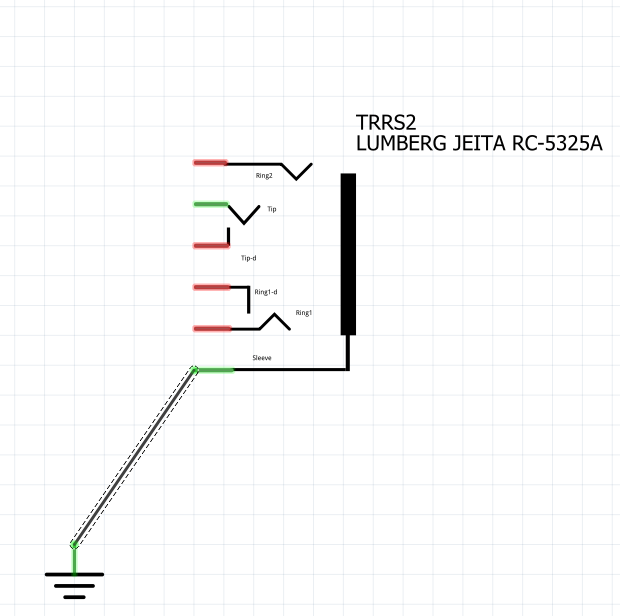
Hello, I am newbie in using Fritzing. I generated a new part (a 3.5mm stereo Jack), but as I tried to use it I found that a couple of terminals (“sleeve” and “tip”) seem somehow internally shorted.
As you can see in the pic hereafter reported, although only ‘sleeve’ is grounded, ‘tip’ also results colored in green as if it was connected (same happens if I connect only ‘tip’: in that case also ‘sleeve’ gets colored as if it was connected too).
I should have uploaded the fzpz file that from another post I understood could allow to troubleshoot where the issue is.
I’d really appreciate any help may arrive from the community members, otherwise I’m afraid my short career as a Fritzing would have already come to an inglorious end…
There is a bus (internal connection in parts editor) between connector0 and connector2 that you probably don’t want. I don’t use parts editor, and I don’t know of a way to remove a bus connection in parts editor (but there may be one!) For this part I edited the part.albe_f55c683d021816305e13ff8763302f7a_5.fzp
in the unzipped .fzpz file and removed the bus definition:
ran it through FritzingCheckPart.py to clean it up (and added missing layerIds in breadboard and schematic. Moved the connectors in schematic to be on .1in boundaries and changed the order of copper1 and silkscreen in pcb to produce this new part:
Since I didn’t change the moduleId on this part you will need to delete your current one (and then shut fritzing down to really delete it!) to load this one.
A tutorial on making parts by editing the files is available here:
thanks a lot to have digged into my issue!!
(By the way, I hope you live in the hemisphere opposite to mine as you answered about 2AM my time
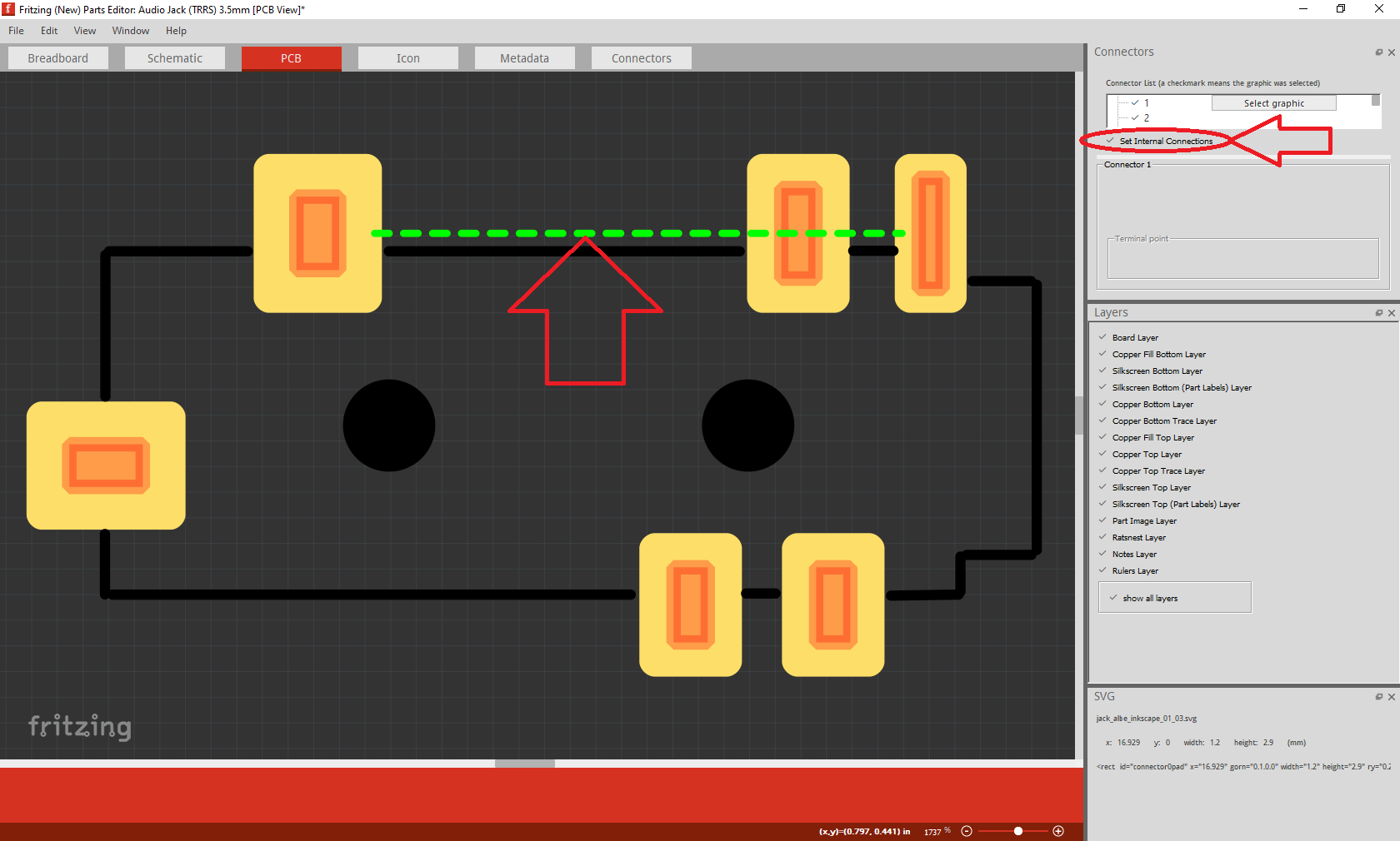
Based on your suggestion, I tried to see if part editor allows to untangle those two signals.
To do that, in the ‘Connectors’ window (on the left in the pic below) you have to check the ‘Set Internal Connections’ button, and the unwanted (in my case) connections become visible:
Now you can point the dashed green wire, push the mouse right button and delete it.
…still don’t know how I happened to connect them originally but never mind.
In case you want to connect two pins on purpose, you have to click on mouse left button while above to first pin and release it while above the second pin.
While I at times have posted at 2AM, this time was during the day . I have made note of how to delete buses with parts editor in case it comes up in future. Thanks!

 . I have made note of how to delete buses with parts editor in case it comes up in future. Thanks!