Sometimes, when using components in several projects, it can be redundant to place and wire-up those components on breadboards each time. Here is a small, step-by-step tutorial on how to create your own reusable plug-n-play modules. We will be using the 555 timer as an example.
-
Start a new sketch in Fritzing.
-
In BB view, click on the full+ breadboard and change it to half+.
-
On the top menu, select File->Export->As Image->SVG. Supply a filename and export the image.
-
Bounce to PCB View.
-
From the CORE bin, scroll down to PCB view, click the icon for Silkscreen Image and drag it into the view.
-
In the Inspector, scroll down and click the Load Image button, locate the breadboard image you exported from step 3 and open it. The breadboard should be imported:
-
In the Inspector section, with the image selected, place the breadboard on silkscreen bottom. The breadboard will appear flipped, but that’s OK.
-
On the top menu, select View->Set Grid Size and set the grid size to 0.01mm. This is important, as that resolution will allow you to accurately place headers over the breadboard image.
-
From the CORE bin, scroll down to Connection, click on Generic Female Header 2-pin, and drag it over the breadboard image, change it to a male header, and rotate it 90 degrees.
-
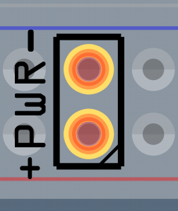
Zoom in close and carefully move the header over the power rails of the breadboard image:
-
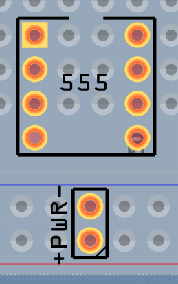
Add and any additional components and arrange them over the breadboard. Don’t worry about them not lining up with the breadboard holes. The important thing to keep in mind here is that you’ll need to reserve some breadboard holes for interfacing with your PCB:
-
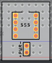
Move and resize your “virtual PCB” over the breadboard image. Important here is you leave your PCB off the breadboard some so it can be selected instead of the underlying breadboard image. Set the width and the height separately.
Setting the width:
Setting the height:
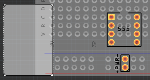
Now move your PCB into place over the breadboard image. -
Add other generic headers, set them for the number of pins you’ll need and carefully place them over the breadboard image:
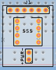
-
Left-click the mouse, hold down the button and mouse-box around your PCB to select it. This will select the breadboard image as well, so hold down the CTRL key and click the breadboard image to de-select it. Then, with the arrow keys, move your PCB from over the breadboard image:
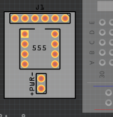
-
Using the silkscreen text tool, label the interface headers and route route your traces. I’ve found that the labels work better when the text height is set to 1.3mm:
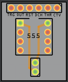
-
Mouse-box around your PCB to select it and all components, and, using the arrow keys, move it back over the breadboard image to check for accuracy:
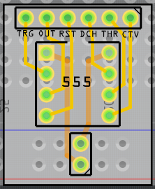
If all is OK, you can now delete the breadboard image. Your PCB is now ready to export for etching:
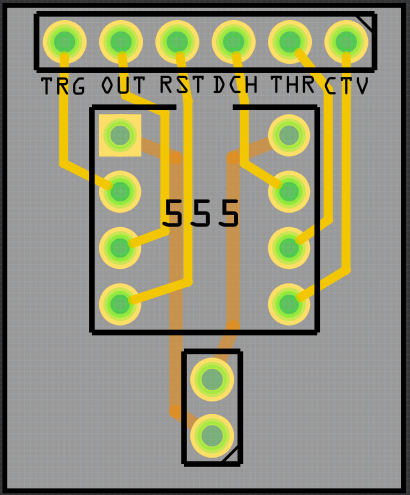
Happy Module Making !!
