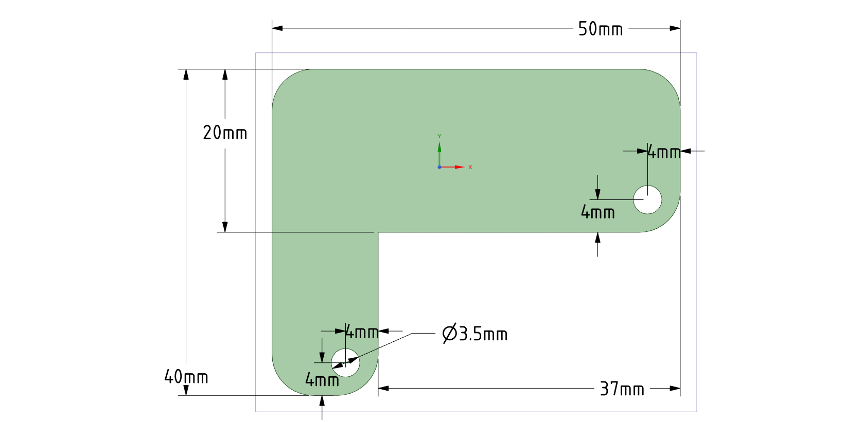
I tried to follow a couple tutorials on creating a custom board shape but no luck. It seems to be far too complicated. Is ther an easier way, a program, or people willing to design custom shapes? Here is what I am trying to make.
I can get to this in Inkscape

which looks like this
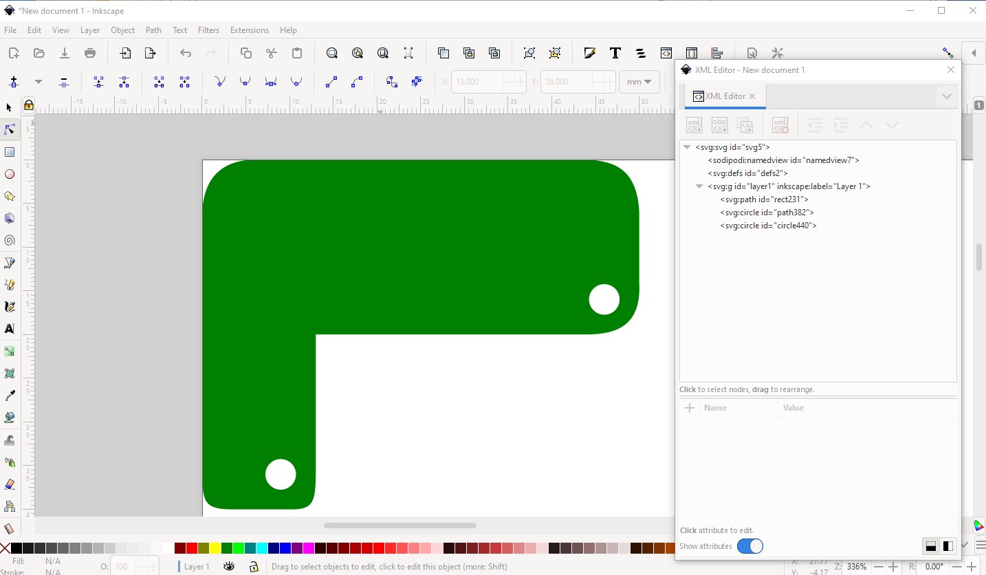
(a path and 2 circles.) In theory I then Edit->select all and do a Path->difference and it should (I think!) convert the 3 items to a single path which it sort of does. What it does for me is convert one circle but not the other and I don’t know why (or enough about paths to know what to do about it!)

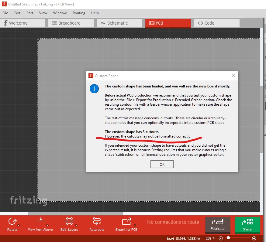
note here the second circle is missing (presumably because the difference didn’t work correctly) and Fritzing reports an error (and only one hole)
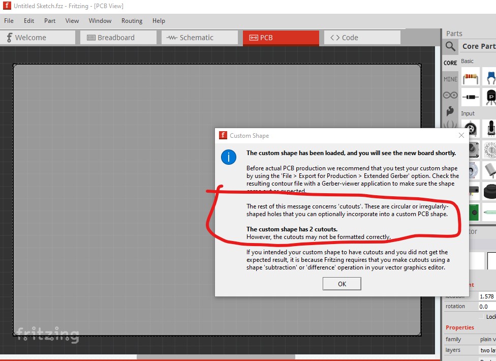
and as it indicates, the result is incorrect
perhaps @microMerlin (who knows a lot more about path creation than I do!) can help? Note as well you probably will need Fritzing0.9.10 to get this to work as there are a bunch of fixes around rendering in that version.
edit:
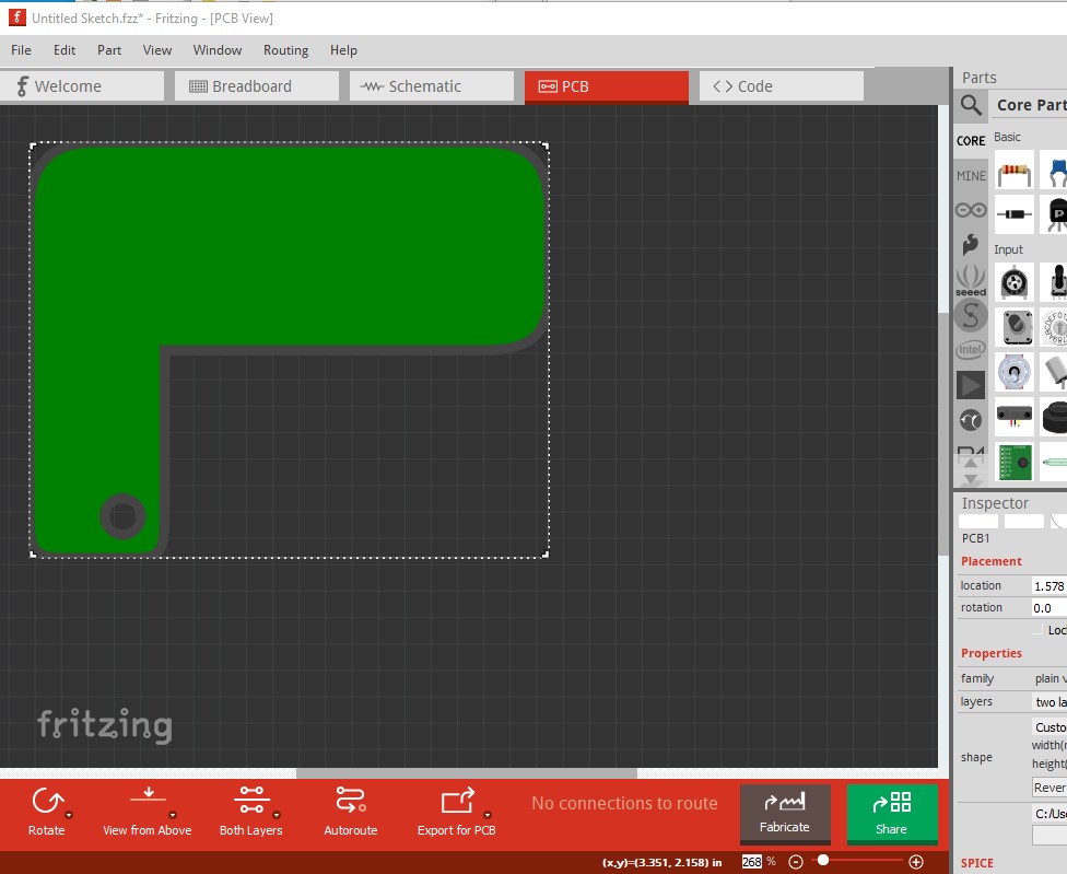
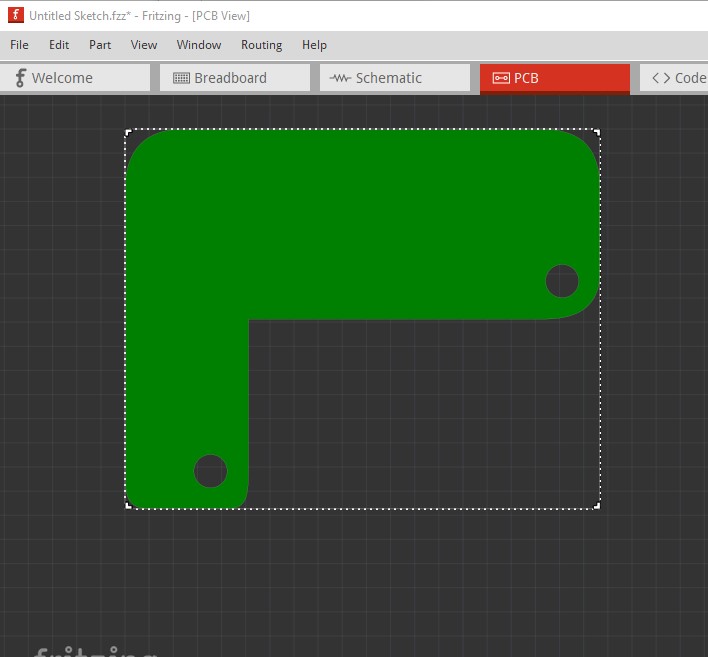
OK trial and error to the rescue! I found what I needed to do was select the two circles and do path->combine to get them both in a single path. Then a Edit select all (to select both the path and the 2 combined circles) followed by Path->difference to create a merged path, It looks like it will only diff the first two paths ignoring the second circle! So for multiple circles in a path, draw the circles then select them and do path->combine to get them all in to a single path, then path->difference the path and the combined circles will work in Inkscape. While Fritzing still complains
it appears to load a correct outline
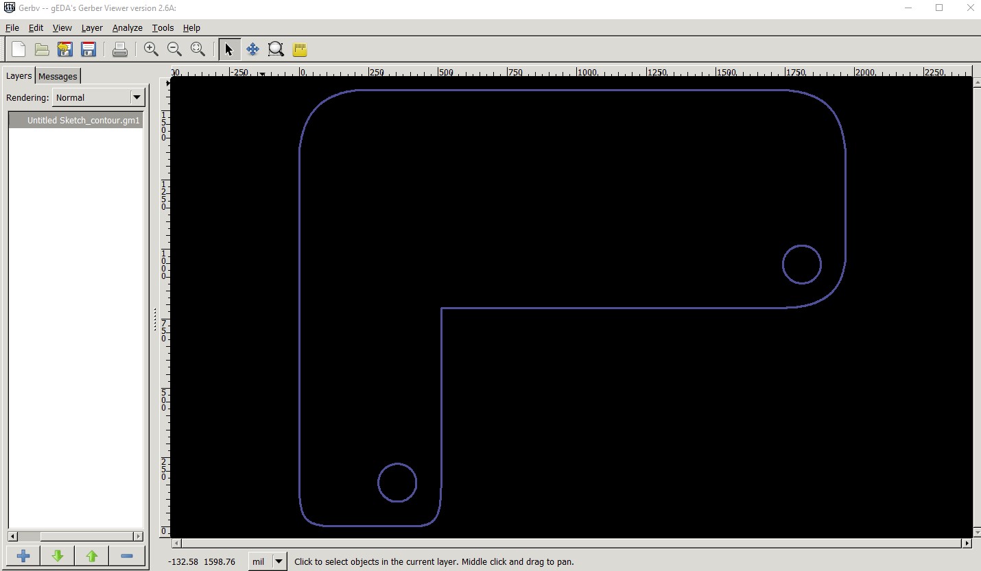
which in turn appears to export to gerbers (this is outline.gm1 displayed by gerbv) Note this was done on Fritzing 0.9.10 earlier versions may not be as successful.
this was created from this svg (right click and “save image as” to download it!)

I would suggest printing out the geber outline.gm1 file at 1:1 scale (I have no idea how to do that however ![]() ) and checking that the result is what you expect. I think it should be correct though.
) and checking that the result is what you expect. I think it should be correct though.
Peter
Here is a version with 4mm radius circular arcs for all of the rounded corners, and exact coordinates everywhere. This image uses mm dimensions instead of in. This loads correctly (gerber export not tested) in Fritzing 0.9.6. Fritzing correctly only sees 2 cutouts. It was not obvious why the older version showed 3 cutouts.

The details of how I created this are probably not useful. I created it manually with a text editor, not a graphics program.
Thanks, I’ll compare mine with yours and see if I can figure out the difference. I’m using the latest version of Inkscape and I’m wondering if it either has a bug in path differenceing or if I am doing something wrong. I may also try an older version of Inkscape and see if that works better (which would point at an Inkscape bug.)
Peter
Comparing could be tricky. Your path used bspline instead of arcs, I started my path at the right angle corner in the middle, and my path uses all relative offsets not absolute.
1 Like
This worked perfectly for me. Thank you very much guys! Hopefully, it will be easier to do this in future versions of Fritzing.
Thank again for the help!