In the PCB view, I would like to create a Jumper, so I can solder external wires and therefore create one sided PCBs that I mill myself.
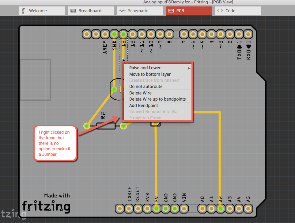
Fritzing’s instructions (here) say to "right-click a Rat’s nest wire and choose “Create Jumper from Selected Wire(s)”. The problem I’m encountering is that when I right click on the rat’s nest wire, no such option to “create jumper” actually is offered to me.
Frizzing also says you can "just right-click on the trace and choose “Create Jumper from Selected Wire(s)”, but once again when I do that this option is not offered.
Thanks for your response Old_Grey. Much appreciated.
According to Fritzing’s instructions, “Jumpers are connections that need to be soldered with external wires. These are shown as blue connections while traces are shown as orange ones.”
I want to turn some of my orange and yellow traces into these blue wires. My understanding of Fritzing’s tutorial and Simon Monk’s instructions in his fritzing book is that you can right-click on either the trace or rat’s nest line and there should be an option to turn that selection into a blue Jumper wire. Meaning, no trace is actually placed on your design. But Fritzing knows you intend to create that electrical connection in the real world and gives you the blue jumper as a cue in your design that that’s what you’re doing.
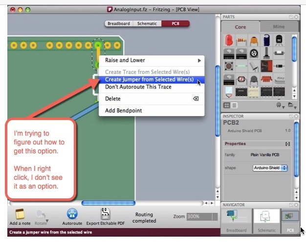
This is what Fritzing’s tutorial image shows, but I can’t recreate.
I suppose I could just not put a trace there at all, and Fritzing will export Gerbers that my mill will cut the same way as if I had gotten the blue lines in Fritzing. But I’d ideally like my design to be correct in Fritzing so I (a) have a record of what I"m doing and (b) in case I ever design something worthy of sharing with others.
Or maybe I’m misunderstanding something about the process. Thanks again to anyone with help. I feel like I am probably making a beginner’s mistake, or maybe a recent software update changed the UI.
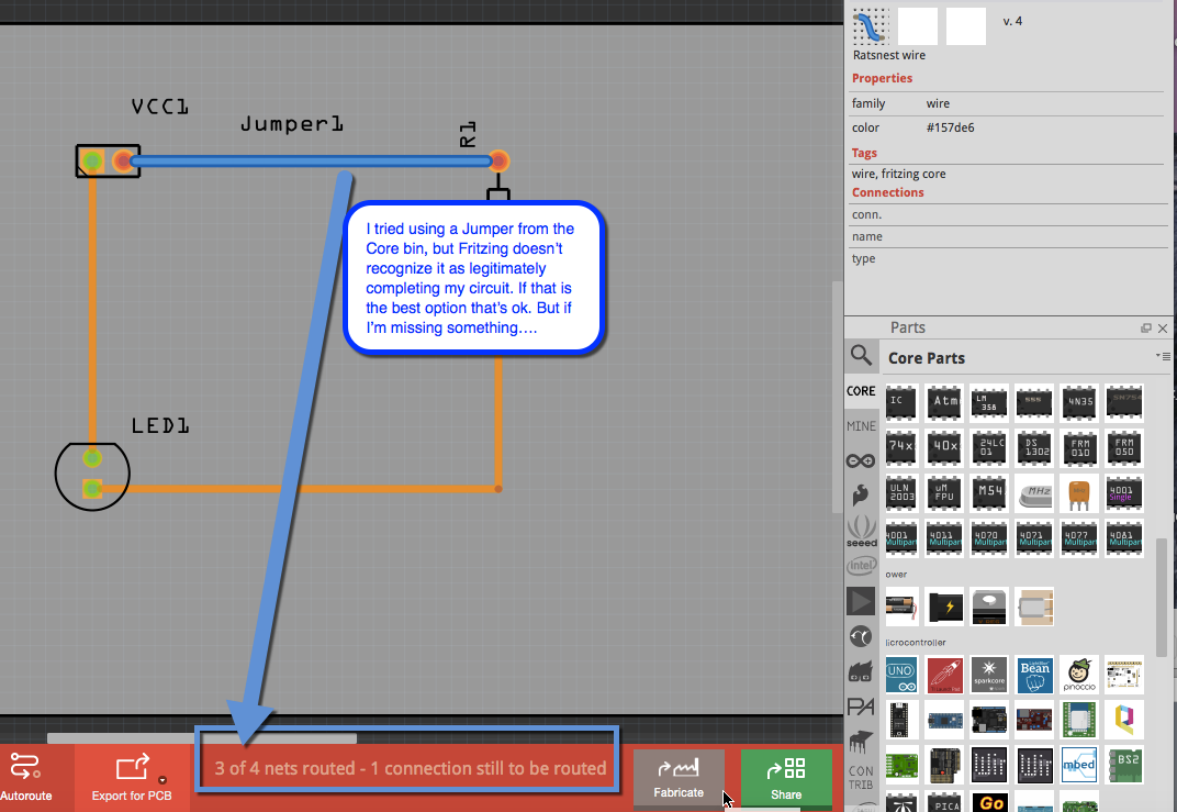
I tried using a Jumper from the Core bin, but Fritzing doesn’t recognize it as legitimately completing my circuit. If that is the best option that’s ok. But if I’m missing something….
I’ve never seen that option, maybe it’s from an old version
You need little traces joining to the jumper, because in real life you don’t put a component leg and a trace wire into the same hole. Fritzing has a kind-of real time EDC, in that the connections will be red if there isn’t a connect, and green meaning it’s connected.
Thanks. It sounds like I misunderstood the book’s instructions, since if you don’t remember that feature it probably never existed. Thanks for the tip on creating a short trace connecting my component leg hole to the trace wire hole. That answered my next question!