Ability to use components allocated in the schematic view for the breadboard or streapboard ,
if it’s possible .
I think it’s possible.
You can save it as a new part, pull the SCH view svg from it and load it back into BB view.
Excuse-me but i don’t understand very well …
Could you explain a little more … with a resistor for example
Right-click resistor in the Bin and select Edit Part, and File/Save as New Part
Go to SCH view, then select File/Show in Folder.
Right-click the highlighted resistor and copy and paste to another folder.
Go to Part Editor BB view and File/Load for View.
Check pin assignments and save.
Thank you so much for this tutorial !
I am very disappointed, I tried the tutorial several times but without success.
I’m not very good …
Could you send me the part if I give you my e-mail by Mp ?
(I know how to add a component in the store)
Post the .fzpz part here with the 7th button above and I will put the SCH in the BB view.
I don’t know if i have been clear at first …
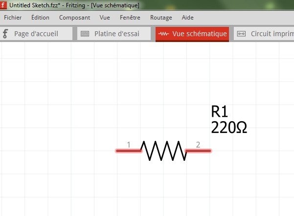
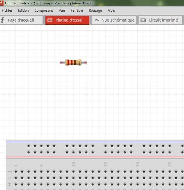
Here is an example :
I would like to use this icon (which is translucent)

in place of that :

in the breadboard wiew or streapboard wiew.
It wasn’t as easy as I thought, I had to copy SCH svg nodes to the BB svg.
Resistor_SCH-BB.fzpz (5.4 KB)
C’est super !
Congratulations, it’s exactely what i’m looking for !
How many time have you spend for creating this part ?
Do you think it’s possible for me also to built some others (like transistor, led, capacitor,diode … ) ?
If you know how to use a svg editor, ie Inkscape, it’s not hard, but if you don’t know, it is hard.
Ok, i don’t know how to use svg editor and Inkskape , only Photoshop 
I thought it was enough to change of place the data from one folder to another …
Never mind !
I’m happy to see that it’s possible to modify the icons BB like this , and perhaps other people will be interested by your work .
I think Photoshop is raster based drawing, where as FZ needs the very different vector based drawing. In theory you could draw with just lines of XML code.
If you know photoshop, you will find Adobe illustrator or Inkscape easy. The only hard thing is figuring out where are the common option at each program, like pencil, layers, etc.
I don’t feel able for this kind of realization because I don’t know enough English.
And google translation is not practical for tutorials or software.
This would be just for the most common components like capacitors, transistors, switches, LEDs, trimmers …
I hope someone will want to pursue the idea !