TMC2209 and TMC2226
TMC2226.fzpz (11.8 KB) TMC2209.fzpz (12.3 KB)]
TMC2209 and TMC2226
TMC2226.fzpz (11.8 KB) TMC2209.fzpz (12.3 KB)]
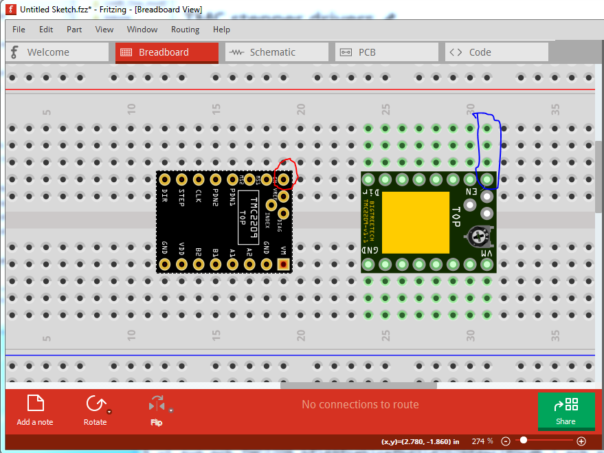
Welcome aboard! The parts are mostly fine with only a few minor issues. First, be lazy  , I made a tmc2209 and a bigtree version for someone a while ago. A google search for “fritizng part tmc2209” would have found them and saved you some work. On to your tmc2209 part, first the pins in breadboard in the fzp file are set to pad. They should be set to male except for the 3 middle pads which should be set to female (or pad, although I’m not sure what pad is for!) This is your part on the left and my part on the right in breadboard (and on the breadboard):
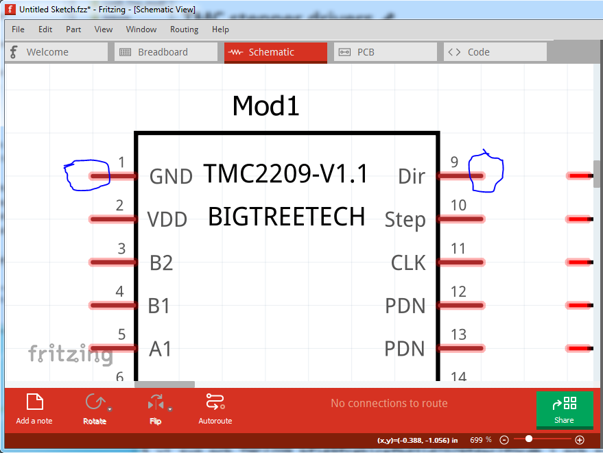
because the pin type is set to pad in the fzp file, the pins on your board do not connect to the breadboard (note the associated breadboard pins are not green to indicate a connection as my part’s are.) You will note the middle pad beside en, is not green because the pin definition is female to block it from connecting to the breadboard and shorting (hopefully there is not a pin in that pad on the real board!) Moving to schematic on my part:
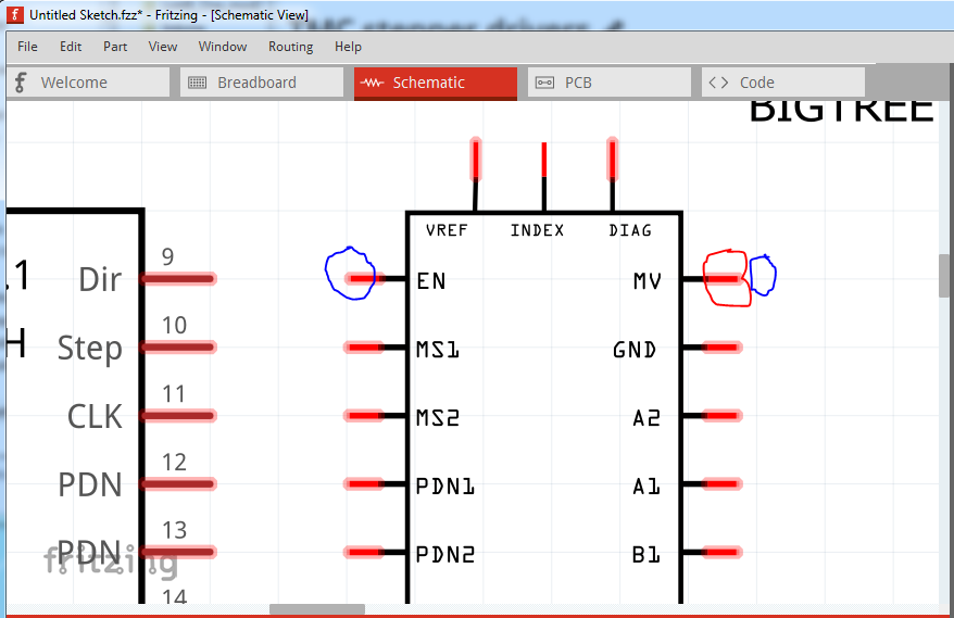
we see that the end of the pins align exactly to the .1in grid (which all parts in schematic should.) On your part:
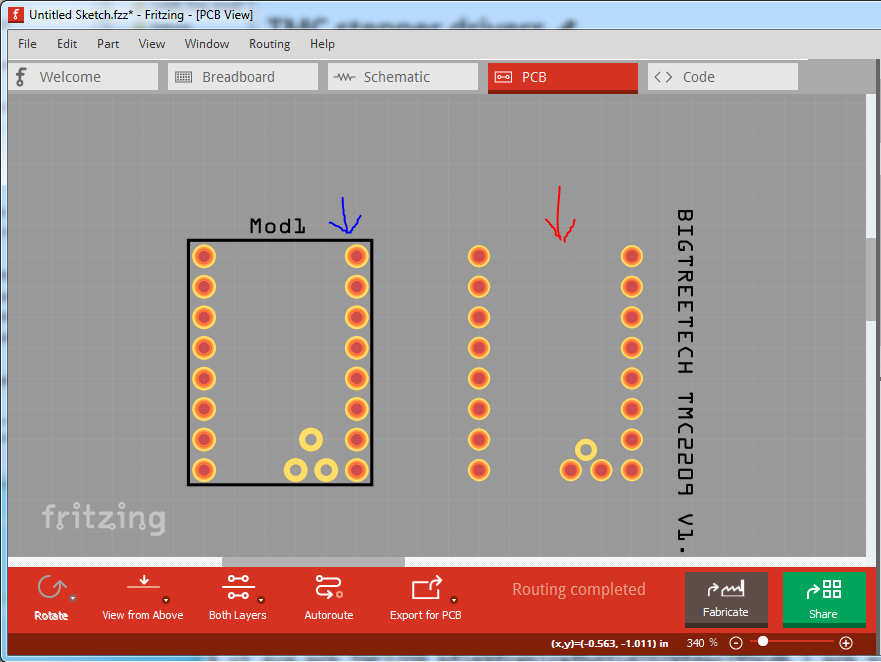
the left side is correct, but the right side is a little short of the grid line (circled in red.) which is undesirable. PCB is mostly fine except it could use the board outline in silkscreen which is missing. In this particular case it isn’t all that important because the pads closely define the layout of the board, but in the general case, the physical outline of the entire module is desirable to insure proper spacing from the other components on the board (especially when the module extends well beyond the pins!)
Peter
Thanks for your comments and tips for improvement, Peter.
Before yesterday I had zero experience in this matter.
As for being lazy, I definitely tried that before starting on this mission.
I must have used the wrong searches, because I didn’t find your part.
Would have spared me a lot of work and a really excruciating headache 
I’m going to improve the parts (if only for myself) regarding the issues you pointed out.
Paul
PS Should I remove the parts from the posting?
I don’t think ‘pad’ is really valid, though Fritzing might treat it the same as female. The connectors here are defined a bit unusual in the fzp file. For example (from the other TMC stepper part):
  <connector type="pad" name="ENABLE" id="connector130">
   <description/>
   <views>
    <breadboardView>
     <p svgId="connector130" layer="breadboard"/>
    </breadboardView>
    <schematicView>
     <p terminalId="connector130terminal" svgId="connector130" layer="schematic"/>
    </schematicView>
    <pcbView>
     <p svgId="connector130" layer="copper0"/>
     <p svgId="connector130" layer="copper1"/>
    </pcbView>
   </views>
  </connector>
For starters, the connectors numbers are from 130 through 149. The first connector should be number 0 (zero), and increase from there. Then the svgId values are the same as the connector id. That works, but more usual is to add a suffix, which is where the “pad” could go (especially for pcb view). Then the connector name is a full word, and the description is blank. Here is a variation that is closer to what I am used to seeing. The svg files would need to be changed to match.
  <connector type="male" name="EN" id="connector0">
   <description>Enable</description/>
   <views>
    <breadboardView>
     <p svgId="connector0pin" layer="breadboard"/>
    </breadboardView>
    <schematicView>
     <p terminalId="connector0terminal" svgId="connector0pin" layer="schematic"/>
    </schematicView>
    <pcbView>
     <p svgId="connector0pad" layer="copper0"/>
     <p svgId="connector0pad" layer="copper1"/>
    </pcbView>
   </views>
  </connector>
In addition, FritzingCheckPart reports that the “breadboard” and “schematic” layerIds are missing from the svg files. They need to exist, or part can end up being excluded from exports to svg files.
connector131terminal in the fzp file is missing from the schematic svg. It looks like the element is there, but the id attribute got dropped.
The ‘pin’ lines in the schematic should be 0.1 inch long. They should cover (or replace) the black lines.
It appears to be valid, I just don’t know what it does. It is one of the radio button options in parts editor along with male and female :
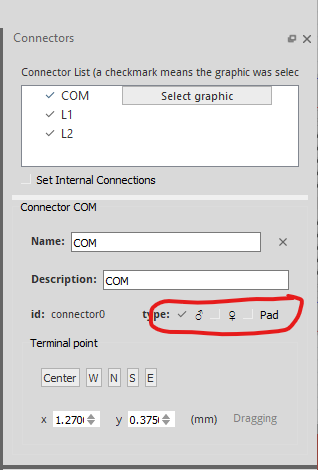
I just don’t know what it does. My guess is something SMD related although I can’t think what. It does get treated as female (or at least not as male which may be the correct case) in terms of connection to the breadboard.
Peter