This part has a number of problems. The svg dimensions are set to px which is likely causing a scaling issue. Here in breadboard the pins are not on 0.1in boundaries, likely because of the scaling problem (or because the source was a 2mm grove connector which doesn’t have 0.1in spaced headers!) As well the viewbox attribute is missing in the breadboard svg and there is no layerId (and thus the part won’t export as an image from Fritzing.)
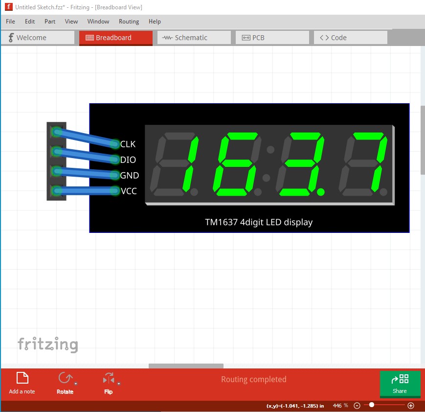
the wires should likely connect straight to the connector. In schematic, the svg lacks terminalIds and thus the wire connects in the center of the pin (which is incorrect) rather than the edge of the pin which is desirable. Again it is dimensioned in px rather than in or mm, but in this case the scale looks to be correct. That will change if you edit the svg with a current version of Inkscape however as Inkscape is likely using a different DPI value. Pcb does not reflect the layout of the part but rather a grove connector. It should show the outline of the part. It too is dimensioned in px and thus is likely the wrong scale (although it may also be a 2mm grove connector and thus the right scale but wrong for this particular part!) In either case the svg should be rescaled to be in in or mm.
Peter
