can someone help me create?
You look to be in luck, there are Eagle files on the TI site. From that Eagle2Fritzing should be able to make a part. I’ll poke at it (as I have Eagle2Fritzing.)
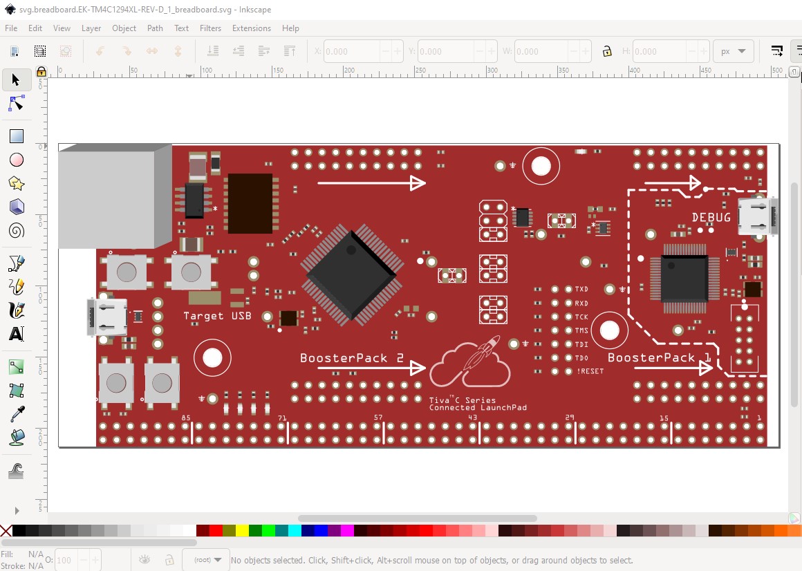
edit: spoke too soon, the generated breadboard file crashes the current version of Inkscape. I’ll back off to an older Inkscape version and see if that helps.
Peter
Thank you very much, I will be waiting.
While breadboard is pretty much done (although the connectors need to be renumbered once I figure out what they all do)
so it may be a few days yet as there are a lot of connectors
Peter
I haven’t forgotten you. This is a complex part with some 220 connections which is a lot of work. Schematic is about one quarter done now, but I need to find pin names and assign pin numbers and insert pin labels which is going to take a while.

Peter
Hi Peter, thank you so much, i don’t know if this can help you https://energia.nu/pinmaps/img/EK-TM4C1294XL-FRONT.jpg
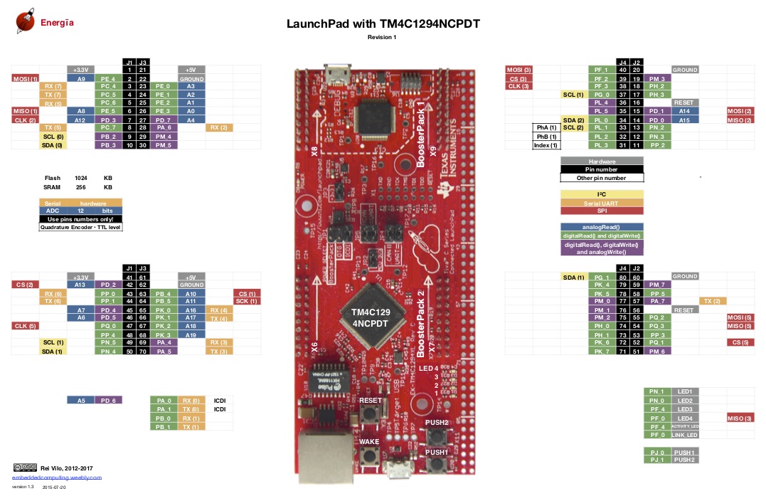
The TI documentation is fine, the issue is from eagle2fritzing. It (because it doesn’t know what connectors are valid) adds connectors for all the ICs as well as the pads (and not all the pads are useful to Fritzing) So I need to translate the eagle2fritzing pin numbers in to the final pin numbers (which need to be in order) for Fritzing like this (note they aren’t indented correctlty!):
Eagle2Fritizing bus definition:
 <buses>
 <bus id='vbus'>
 <nodeMember connectorId='connector100'/>
 <nodeMember connectorId='connector102'/>
 <nodeMember connectorId='connector104'/>
 </bus>
 <bus id='+3v3'>
 <nodeMember connectorId='connector105'/>
 <nodeMember connectorId='connector107'/>
 <nodeMember connectorId='connector560'/>
 <nodeMember connectorId='connector600'/>
 <nodeMember connectorId='connector640'/>
 <nodeMember connectorId='connector737'/>
 </bus>
which needs to be translated to this:
 <buses>
 <bus id='vbus'>
 <nodeMember connectorId='connector173'/>
 <nodeMember connectorId='connector175'/>
 <nodeMember connectorId='connector179'/>
 </bus>
 <bus id='+3v3'>
 <nodeMember connectorId='connector0'/>
 <nodeMember connectorId='connector97'/>
 <nodeMember connectorId='connector167'/>
 <nodeMember connectorId='connector176'/>
 <nodeMember connectorId='connector199'/>
 <nodeMember connectorId='connector219'/>
 </bus>
Note there are only 220 connectors in the Fritzing part (0-219) so the numbers in the 600 and 700 range in the eagle2frtizing file need to be translated which is what I am currently doing. It is possible to do this with a script that reads the eagle2fritzing fzp file and keeps a translate table of the eagle2fritzing pin numbers to the Fritzing final pin numbers (which are already generated in a script) but I haven’t done that yet and so am doing this manually. The buses are the last step before testing the final part so it shouldn’t be too long for a part, as long as I haven’t made any errors.
Peter
Finally finished. Here is the part and its test sketch. The test sketch is fairly ugly as I was only interested in correct connections not layout or looks. Note the debug connector doesn’t have a presence in pcb (because it is SMD and eagle2fritzing didn’t recognize it as this is a through hole part!)
the part:
TI Launchpad EK-TM4c1294xl.fzpz (70.2 KB)
and its test sketch:
test-Sketch.fzz (160.9 KB)
I didn’t verify all the buses because schematic is too large to make that easy. If you click on a bused pin the other pins in the bus should light yellow (and I normally verify that to make sure the bus defs are correct) but in this case schematic is too large to make that easy so I just assumed the buses are correct (which they may not be!)
Peter
1 Like