I put together a simple ATmega circuit to run arduino code. I am wondering whether I set my pcb up in a good way or is it ass backwards and shitty. thank you guys.
<img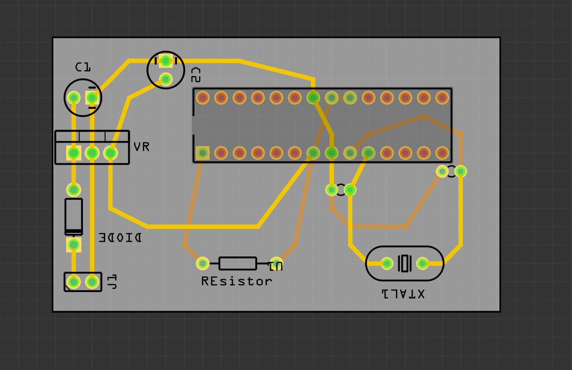
I hardly know what Im doing so any tips would be appreciated 
I put together a simple ATmega circuit to run arduino code. I am wondering whether I set my pcb up in a good way or is it ass backwards and shitty. thank you guys.
<imgI hardly know what Im doing so any tips would be appreciated
Not a bad attempt, but your diode appears to be in backwards (the cathode needs to go towards the voltage regulator to conduct). The leads on your crystal are also too long (I’m assuming a standard 16MHZ crystal). You want the leads from the crystal to be as close to the pins they connect to as possible and probably on one side of the board. I assume this is only an exercise (i.e. you don’t actually plan to make this) as there are a number of things missing to make it a practical usable board and in any case a Promini from ebay for a couple of bucks would likely be a more economical choice.
thanks for the reply, very informative! Yes this is only an exercise (at least at the moment it is). I would like to actually fabricate this design sometime in the future but of course I want to make it perfect. Could you tell me what is missing from it to enable it to be a practical ATmega circuit? Or do you possibly have any links to somewhere I could learn? Thank you!! 
As I said, it is likely more economical to buy a module off ebay or sparkfun (the entire module is likely cheaper than you getting a single board), however if you want to do it as a learning experience there isn’t any reason not to do it other than cost (and learning always costs anyway!). Off the top of my head (meaning there are probably things I know you should do but have currently forgotten ): the reset circuit of only a resistor won’t work in the real world. At power on the reset will go instantly high and not actually reset the chip. In a standalone circuit there is usually a largish capacitor (1 to 10 uf) from the reset pin to ground. That at power on holds reset low til the resistor charges it up resetting the CPU and then starting it.You should have bypass capacitors (typically a .1 uf ceramic in parallel with a 1 to 10 uf tantalum) as close as possible to the power and ground connections to the CPU (as when ports are switching there are high current draws on the power pins which can pull down the supply voltage and cause problems). You likely want a set of .1 inch connectors for each of the CPU I/O pins so you can connect things to it. You likely want to provide a method to program it (either via a serial port and the Arduino bootloader or via the isp pins) unless you are going to load the program externally with a programmer and plug the CPU in with a fixed program. Looking at the Arduino Uno schematic (available on the Arduino site ) should give you some hints about how they do it (although thats a lot more complex than what you are currently doing). If there are any pro mini schematics (check the sparkfun.com web site) that is probably closer to what you are trying to do.
Your the best!! Thank you so much.yes im really just teying to learn how hardware works. (Im more of a software guy) so a learning exercise this is. Thanks again.
It really is good to know both. I trained originally in hardware and switched to software about 5 years in (in microprocessors) 40 or so years ago and being able to sketch on a napkin the circuit that did what I needed (when the hardware guy said it wasn’t possible) came in handy more than once. As did understanding what the hardware was doing under the covers while doing systems programming on IBM mainframes.I’m lucky enough to have started when if you wanted a function you had to build it yourself from ttl gates (and thus had to know how it worked at a very basic level). If you have more questions feel free to ask.