Hello.
Does anyone have an part for the Ethernet kit of Teensy 4.1,or the schematic?
There appears to be a schematic here
https://www.pjrc.com/store/ethernet_kit.html
there doesn’t appear to be a fritzing part for it (but it also isn’t particularly useful.)
Peter
The image that appears to be an schematic is very small
It is also very simple and (other than the header pinouts) reasonably clear.
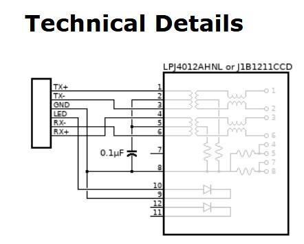
As I recall the header pin outs are documented in the Teensy documentation with the signal names. This should give you anything you need.
Peter
But I dont found this parts Link-PP LPJ4012AHNL or Cetus J1B121 J1B12111CCD .
At least with the same pins.
Odd because a google search for “LPJ4012AHNL” turns up several references to the part. Google is your friend.
Peter
I mean I dont found this part to use in fritzing . If you found fritzing parts with LPJ4012AHNL please tell me what miracle you do.
There likely isn’t one. There are several mag jacks (search for mag jack in parts search) and one of them may have the correct footprint. If not you would need a custom part. I’d suggest that you would be better to buy the complete module than try and make one though, it is likely to be much cheaper and is known to work.
Peter
i’m in true I’m trying to build an DSP system using 3 Teensy 4.1 interconnected via an switch. I wouldlike to build an pcb with 3 rj45 connector 1 for each Teensy 4.1
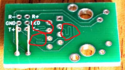
It is unclear to me what you want to do. Assuming you want to connect 3 Teensys to an ethernet via an ethernet switch, 3 built modules for the Teensys to provide ethernet would be the easiest and safest solution. I see from one of the pictures of the ethernet adapter board that they have put what appears to be extra length for skew control on 3 of the traces. Duplicating this in Fritzing is likely to be somewhat difficult (as I am not aware of a way to measure the length of a trace in Fritzing.) Thus you would be best to use three of their interfaces which is know to work with the teensy. The three signal traces circled in red in this image are what I am referring to. That likely makes the length of the traces other than T+ (which looks to be the longest) the same for skew reasons. That will be hard to duplicate and thus using their boards makes the most sense to me since they have already done the work (and tested that it works!)
Peter