I see we got the Teensy 4.1 and other versions on this forum, but the Teensy 4.0 is missing, anyone have the fritzing part or can quickly make it would be greatly appreciated.
If you have a pointer to a mechanical and pin out drawing for the 4.0 it is easy enough for me to modify one of the other versions to match.
edit: found the mechanical and pinout drawings. A part should be up in a couple of days.
Peter
This should do what you need:
edit (Oct 2023)
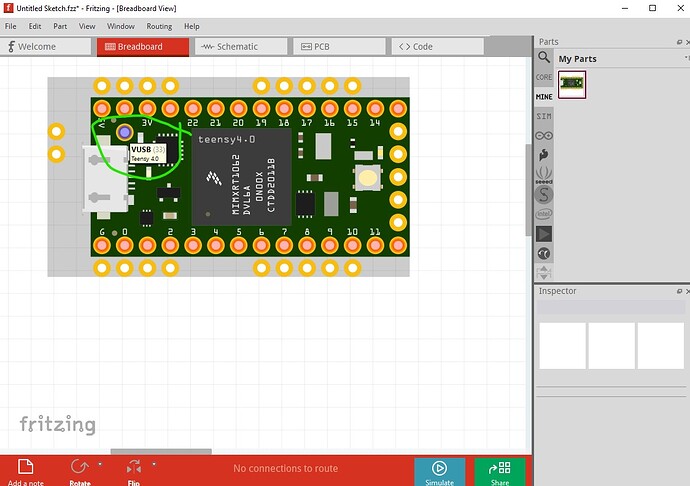
Replaced the part with one with the VUSB (but none of the other bottom pads which are in a post further down if you need them!) defined as well.
teensy-4.0.fzpz (14.6 KB)
Peter
thank you, its awesome
Do you have a file for the teensy 4.0 that has the back part of it as well?
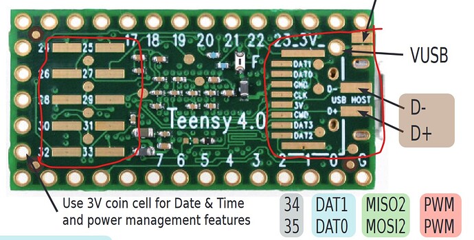
Assuming you are referring to the SMD pads on the back side of the pcb, no. It isn’t easy to mix through hole and SMD in a Fritzing part and since there appear to be SMD components on the bottom of the board I’m not sure how you would connect to the connectors other than wires soldered to the pads. I’m assuming you want access to some or all of the connections circled in red in this image (which is from this web page)
They will be difficult to add in breadboard since they are on the bottom of the board and as noted because of the components on the bottom of the board it doesn’t look like you could use SMD pads to make connections in pcb. I suppose we could put them on the top of the board in breadboard (which won’t match real life) and suppress them in pcb and assume you will solder wires on to them though.
edit:
Here is a part that should do what you want. It is fairly ugly, but the bottom connectors are brought out in breadboard and in pcb (to pads.) In order to use it on a pcb you need to solder a wire to the pad on the Teensy then route the wire to that appropriate pad on the pcb,
teensy-4.0-bottom-pads.fzpz (16.6 KB)
Peter
Thanks you, this will work perfectly for me.
There are T4 breakout boards made by the community already,
find out details here, the most hardest part I guess is the SDIO-interface soldering
Mr. Vanepp, I’m a high school teacher and I love all of your helpful posts. We use the Teensy 4.0 in class, Would you please at the 5v VUSB connector on the Teensy 4? We use it to provide power to Neopixels. 5V VUSB is available on Teensy 3.2, however, it is not on Teensy 4.0
Thanks you,
Frank G
It is there on the teensy-4.0-bottom-pads.fzpz part 3 posts above this.
but it is easy enough to add to the Teensy4.0 part (without the other back side pads which add clutter if not needed) I have done so and will update the original post of the Teensy4.0 (so there is only one copy present!)
Peter
Thank you so Much! I really appreciate the quick response!
Teensy4.0.fzpz (21.4 KB)
Here is a modification of the VanEpp Teensy4.0 Fritzing part that I need for making a PCB layout.
I have removed the upward pins that make it more friendly for laying out PCBs.
Hopefully this is useful to someone other than me!
Thanks to Peter, this was a much less arduous task than starting from scratch!
Kevin.
The main problem I see is your pcb holes are too small. They appear to be 0.035in rather than the original 0.038 (which is the size of a 0.1in header) and thus likely won’t accept a 0.1in header. From the gerber drill.txt file with both boards loaded:
; NON-PLATED HOLES START AT T1
; THROUGH (PLATED) HOLES START AT T100
M48
INCH
T100C0.038000
T101C0.035000
%
Peter

